1
\$\begingroup\$

I want to use an AC to DC 14.4 V adapter to supply both my circuit and its battery. The circuit works with 12 V and I use a battery during power outages (blackout time).

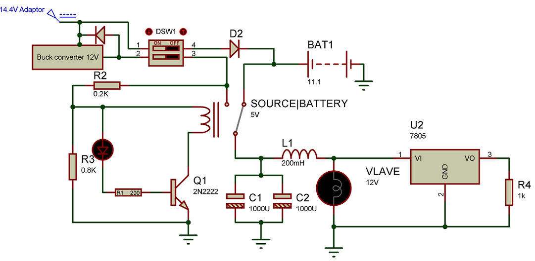
I have prepared the below circuit for switching between adapter and battery, but I need to recharge the battery when power comes on again. Assume the dip switch is the main power key.

Circuit for switching between battery and adapter

The main problem is that if I use an op-amp as a comparator for the battery voltage level, it will show the adapter output voltage, not the battery level. So how can I solve this?

And another problem is: Suppose we are in blackout time and the battery voltage level has decreased to, for example, 9 V. How can I disconnect the battery? Is it possible to use a MOSFET like the IRF510 between battery and circuit?

\$\endgroup\$
7
  • \$\begingroup\$ “The main problem is that if I use an op-amp as a comparator for battery voltage level, it will shows the adapter output voltage not battery level” ...can you explain more why you think this wont work?measuring the voltage across the battery should be okay. \$\endgroup\$
    – Navaro
    Commented Aug 5, 2018 at 10:41
  • \$\begingroup\$ @Navaro Oh really?! Actually i didn't try. I thought it will show source voltage. So if it acts like this, the buck converter input voltage decreases and also we would have another decrease on buck converter output terminal. \$\endgroup\$ Commented Aug 5, 2018 at 15:32
  • \$\begingroup\$ I test it. Charger with no load had 14.4v in output terminal. After i connect it to the battery, voltage decreased to 14.16v. I think its naturally, however output current is low (about 0.5A) and its a chip one. I didn't expect this charger more than this :) \$\endgroup\$ Commented Aug 6, 2018 at 6:12
  • \$\begingroup\$ did you measure the charger output voltage or thr voltage across the battery. my understanding is that the battery voltage is used as input for the op amp. place a resistor of a 10-100ohm between the charger and battery and measure the voltage across the battery. \$\endgroup\$
    – Navaro
    Commented Aug 6, 2018 at 11:13
  • \$\begingroup\$ @Navaro So I should place a 10-100Ohm resistor after D2 and I measure the voltage of battery right after the resistor. Right? Okay I'll test it. Thank you. But Another question. Why engineers are using difficult methods for measuring battery voltage level during charging? For example they disconnect the charger and then they measure it. Or they use Coloumb counting?!!! \$\endgroup\$ Commented Aug 7, 2018 at 8:31

1 Answer 1

1
\$\begingroup\$

there is no problem measuring vokltage at battery if intrenal resistance of battery is low enough (to pull down the voltage of the adaptor).

An additional resistor may help a litle, but if you use a n-channel mosfet-switch at ground level to disconenct charging you can measure both connected and disconnected- so in my point of view no problem there (no additional R needed) . If Mosfet ist disconnecting (due to high voltage level or due to low level (discharged in offgrid state) everything is ok (Mosfet and voltage comparator must be low power to not discharge battery too quick until grisd is on again). IRF510 is 100V, aprox. 5A, so seems ok if current is average current (hwat is the usage of L1 and VLAVE ???)

\$\endgroup\$

Your Answer

By clicking “Post Your Answer”, you agree to our terms of service and acknowledge you have read our privacy policy.

Not the answer you're looking for? Browse other questions tagged or ask your own question.