0
\$\begingroup\$

I have an electric lock that needs 12v to stay in a lock position. It opens on 0v.

I was thinking about controlling this with a MOSFET (IRFZ44N).

Currently I have the following setup:

  • The 12v power supply connected to the source pin.
  • The drain pin is connected to the power wire of the lock.
  • The gate wire is not connected (yet)

With this setup the lock starts in a lock position. So it gets 12v.

Can I control the gate pin by simply connecting it to an Arduino output pin? Can I control this MOSFET with an Arduino board?

If so, is it just a matter of setting the output pin to LOW and HIGH to control Gate?

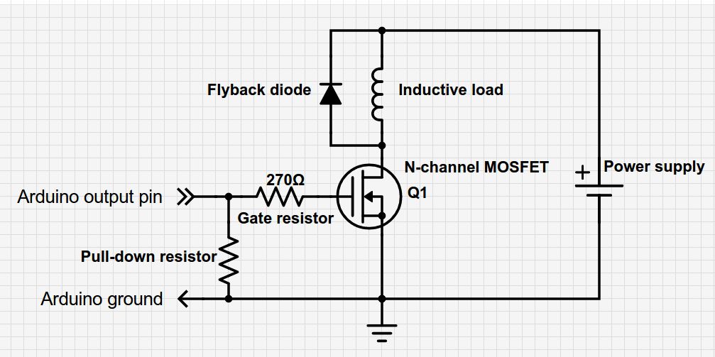
I'm trying to follow this schematic (not mine, just trying to follow it):

enter image description here

\$\endgroup\$
4
  • \$\begingroup\$ There is a schematic button on the editor toolbar. Schematics are much better than words. Add a link to the MOSFET datasheet. (The part number probably uses capital letters.) \$\endgroup\$
    – Transistor
    Commented Aug 5, 2018 at 15:32
  • \$\begingroup\$ Providing you are using a 5V Arduino you can drive this FET directly. If the Arduino is powered from the same 12 V supply you don't really need the pulldown resistor since the Arduino is always running. \$\endgroup\$ Commented Aug 5, 2018 at 15:42
  • 1
    \$\begingroup\$ @Jack: Is the resistor not a good idea to hold the MOSFET off during boot when the GPIOs are tri-stated and floating? \$\endgroup\$
    – Transistor
    Commented Aug 5, 2018 at 15:44
  • \$\begingroup\$ @Transistor. Of course it could be considered belt and braces, both for startup and to hold the gate discharged when powered off. However given that the application requires the MCU to be running and the 12 V power supply to be on ….and that it would only be a single transition to on I said 'you don't really need' the resistor. In addition the gate capacitance is large, and when initially turned on will hold an input gate low for considerable time. If the OP wants to use the pulldown there is no downside, but IMO it is not required. \$\endgroup\$ Commented Aug 5, 2018 at 16:17

2 Answers 2

3
\$\begingroup\$

That MOSFET cannot be safely driven directly by the Arduino output pin. It is specified at 10V and the Arduino (most of them) provide 5V nominal.

A more appropriate MOSFET is the IRLZ44.

Other than that, the circuit is fine, assuming you stay within a reasonable current for the MOSFET (>10A is okay with the one I linked).

\$\endgroup\$
6
  • 1
    \$\begingroup\$ Reference to the datasheet shows the device is capable of at least 1-2 Amps at 5 V drive levels ….why would you need 10V to drive this solution? \$\endgroup\$ Commented Aug 5, 2018 at 15:46
  • 1
    \$\begingroup\$ @JackCreasey The only relevant guarantee on the datasheet is the Rds(on) at Vgs = 10V. Typical curves don't guarantee the maximum drop or power dissipation, so they should not be used in that way for design purposes. Might it work? Sure. \$\endgroup\$ Commented Aug 5, 2018 at 15:52
  • \$\begingroup\$ ….now you are dredging the bottom of the pool. Did you notice the RD(ON) on both datasheets is only specified as a pulse (300 us). This has almost no bearing on the application where it is continuously on. Of course you'd conservatively used the graphs to select an operating point. \$\endgroup\$ Commented Aug 5, 2018 at 16:20
  • \$\begingroup\$ @JackCreasey The Rds(on) is tested at the factory with a short pulse to avoid the effects of the positive tempco caused by heating. I added 50% to the guaranteed value to calculate the (conservative) >10A value. There is good reason to use "logic level MOSFETs" and not general purpose ones when you intend to switch them with a logic level. \$\endgroup\$ Commented Aug 5, 2018 at 16:33
  • 1
    \$\begingroup\$ @JackCreasey I would still use a BJT to drive the MOSFET gate since 12V is available. I agree it will most probably work, but this is suppose to be about Engineering, not hobby tinkering. \$\endgroup\$ Commented Aug 5, 2018 at 17:23
0
\$\begingroup\$

Yes, it's that simple, if you have a 5V Arduino. The maximum threshold voltage for the MOSFET is 4.0V so a 3.3V digital pin might not get the MOSFET fully conducting. Don't leave out the diode in parallel with the solenoid. You might not need the pulldown resistor if the MOSFET's gate is hard-wired to the Arduino, but if you do use a pulldown resistor it can be 10 k\$\Omega\$ or so.

\$\endgroup\$

Your Answer

By clicking “Post Your Answer”, you agree to our terms of service and acknowledge you have read our privacy policy.

Not the answer you're looking for? Browse other questions tagged or ask your own question.