So I'm currently using the design & schematic of adafruit's Powerboost 1000c. I've already discovered in a previous thread about which VBUS lines I can remove but will have to find out what I need to do in order ot access an serial terminal/gui via usb micro but that's for another question.
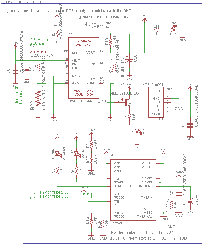
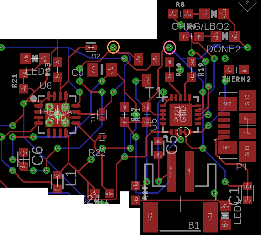
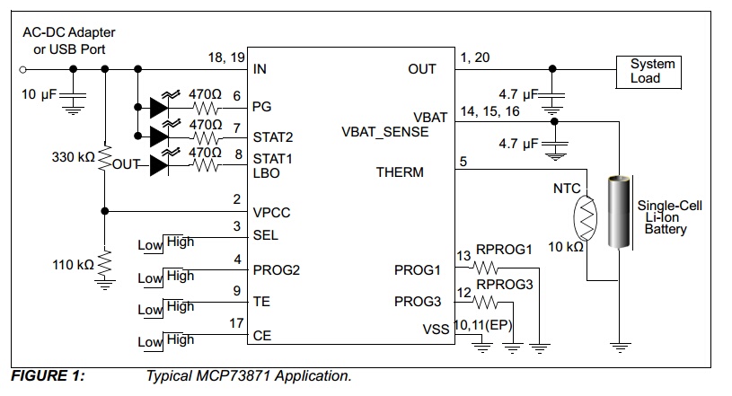
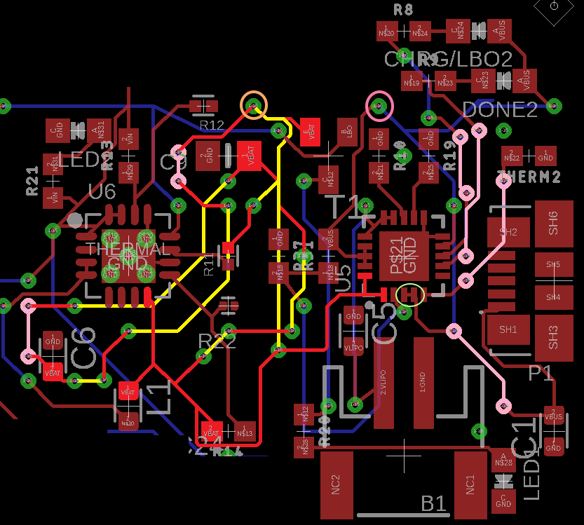
My current question at hand is in the below schematic and board view what VBAT lines do I currently require and what do I not require?
My end priority goal to to be able to recharge the battery which I'm already able to do but whilst also minimzing the amount of vbat in the schematic (by minimize I mean what do I require to make my goals possible and what ones I don't require i.e. I can get rid of). This is because in adafruit's schematic the likes of vbus & vbat connect together and then meet together after connecting to their respective components at their desired pin out with the VBAT pin out depicted by the orange circle and the VBUS pin out depicted by the pink circle.
My 2nd goal is to be able to check the battery level so I can later alert the user in software as to the battery level descending below a specified threshold.
Whether this requires something extra to be added to the schematic I don't know or I can use that VBAT pin and just link it directly to the main computer in my case being a Raspberry Pi Compute Module 3, it would be greatly appreciated if that's the case and you could point that out for me or any alternative routes I will have to take in order to reach this secondary goal.

amount of vbat.... it is unclear what you are quantifying \$\endgroup\$Vbatin the circuit .... you need to determine if a component requires a connection toVbat\$\endgroup\$LED1seems to be an indicator, so it may be possible to remove the circuit associated with it \$\endgroup\$