0
\$\begingroup\$

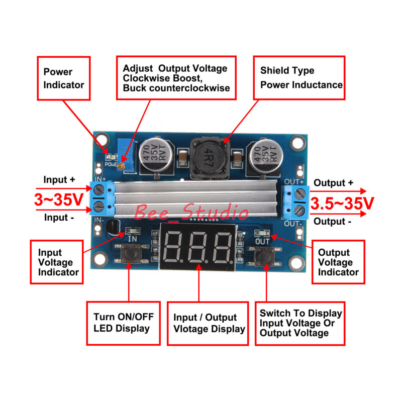
Recently I combined two 18650 batteries in Parallel, and attached the output of the Paralleled 18650 batteries to a 5V Step UP Converter.

Device draws 5V 4a.

Here is a picture to the step up: enter image description here

While the Paralleled batteries are the input, when I set the output on the adjustable converter to 5V and connect my battery powered device, the output Voltage drops to 2.3V and 1.3A.

I am not sure why this is happening: immediately when I connect the battery powered device to the output with AWG Gauge wires, the Voltage I set is seemingly overriden.

Thanks!

Here is the data sheet: enter image description here

\$\endgroup\$
18
  • 1
    \$\begingroup\$ we are still waiting for the answer to all of my questions. \$\endgroup\$
    – PlasmaHH
    Commented Sep 27, 2018 at 13:52
  • 1
    \$\begingroup\$ "Two Paralleled 18650s can provide, say, 15A constantly" that very much depends on the actual batteries used and their condition. I am specifically asking about those that you are using. What does their datasheet say? "Not sure what you mean by drop" I mean what does the voltage of the batteries drop to while being used. You know that they do that, don't you? \$\endgroup\$
    – PlasmaHH
    Commented Sep 27, 2018 at 14:11
  • 1
    \$\begingroup\$ What is the input voltage when the output is dropping? \$\endgroup\$ Commented Sep 27, 2018 at 14:52
  • 1
    \$\begingroup\$ Ok, it appears as if your module does is not able to meet its own specifications. Since you are running at lower voltages than anything in the test data, my best guess would be that this module cannot supply full power with such little input voltage. Note that you are right at the bare minimum input voltage. \$\endgroup\$ Commented Sep 27, 2018 at 15:22
  • 1
    \$\begingroup\$ Those cheap Ebay modules rarely live up to their claims, and expecting 20W output with ~3V in is asking a lot (I doubt the inductor is capable of dealing with the required peak currents). Oh, and about this: "The device rates at a 96% efficiency." - maybe it can do 96% at some specific combination of input voltage, output voltage, and power (although I'm still sceptical). But it definitely won't do it for all combinations, and most likely not for a low input voltage (which happens to be your scenario). All this is partly normal boost limitations, and partly Ebay "marketing". \$\endgroup\$
    – marcelm
    Commented Sep 27, 2018 at 20:32

1 Answer 1

1
\$\begingroup\$

I can only speculate, as you didn't mention what you measured the input voltage at under load (or at least didn't say whether it was under load or not):

You're operating close to the lower limit of input voltage. Your batteries might be at 3.54V with no load, but the battery ESR and state of charge (as well as any wiring between it and the board) might cause it to droop when you pull current. Perhaps there exists an undervoltage mechanism to shut down the supply when the input is too low. If so, it would kick in and shut down the regulator, which would result in...that's right, lower current drain. The battery voltage quickly recovers, and at that point the regulator kicks in again.

If this is what's happening, you can measure the voltage at the input of your board and see if it's dropping to <3V when your 5V device is connected.

If that's the case, I'd suggest trying a bench supply, but I suspect this is supposed to be your bench supply. Make sure all your battery wiring is as short and as solid as possible, to eliminate that as a cause. Failing that, try paralleling more batteries to see if it makes a difference.
\$\endgroup\$
2
  • \$\begingroup\$ Hi Cristobol, I measured the Voltage input at the input of my board, as you suggested, and it measured 3.54V. Same problem exists even with a more expensive board with perfect ratings. However, this time, when I connect the output I am measuring a 3V output versus a 2.3V output in comparison to the Ebay board I bought. \$\endgroup\$ Commented Sep 29, 2018 at 18:56
  • \$\begingroup\$ It looks like now, with the new board, the voltage or the input at the board is now the voltage at the output when connect to load. When it's not connected to any load, the board works perfectly. \$\endgroup\$ Commented Sep 29, 2018 at 19:09

Your Answer

By clicking “Post Your Answer”, you agree to our terms of service and acknowledge you have read our privacy policy.

Not the answer you're looking for? Browse other questions tagged or ask your own question.