2
\$\begingroup\$

What I'm trying to do can be best described by the following circuit based on an electromechanical relay:
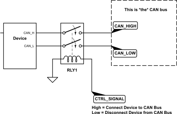
schematic

simulate this circuit – Schematic created using CircuitLab

However, is there a simpler solution not involving any mechanical/moving parts? [[ edit: as pointed out by Lundin's answer, switch bouncing and EMI from the coil could mean that this approach is entirely unsuitable ]]

The "complication" is that CAN is a broadcast bus with open-collector-like connections (not sure whether they are implemented as true open-collector) to emulate a "wired-AND" (any device can assert a logical 0). However, I'm not sure how exactly the physical "driver" (on the device's connection to the bus) is implemented, since it is differential, with states being: both lines at 2.5V for a differential voltage of 0V, and (CAN_H,CAN_L) = (5V,0V) for a differential voltage of 0V (not sure whether it is always like that, but this seems to be one common scheme).

Would a MOSFET transistor acting as a switch do the trick? What about a solid-state relay? Would the SSR be able to transmit the 1Mbps (Megabit per second) signal when in its "closed" state?

Reaction time (time it takes to connect or to disconnect the device) is not important. [[ edit: the intended notion was "disconnect latency"; as long as the actual disconnection happens fast, it does not matter that it takes 100ms from the time we decide that we want to disconnect to the time when we actually disconnect it ]]

\$\endgroup\$
6
  • 2
    \$\begingroup\$ You could use an analog switch (or multiplexer) as plenty of those don't break a sweat at 1Mb/s, or use a driver that can be inhibited, such as the SN65HVD233 \$\endgroup\$ Commented Oct 4, 2018 at 14:30
  • \$\begingroup\$ Driver with EN is not an option (we do not design the device; we want to control connection/disconnection of an existing device). As for analog switches --- are their output stages fundamentally different (in behaviour/capabilities) from those of an SSR? The "simplified schematic" of an SSR shows two (photo-)MOSFETs; analog switches also use a pair of MOSFETs. With an analog switch, do I need to power it with +V and -V that exceed the range of the signal? (i.e., V- < lowest possible signal voltage and V+ > highest possible signal voltage) ? \$\endgroup\$
    – Cal-linux
    Commented Oct 4, 2018 at 15:38
  • 1
    \$\begingroup\$ A lot of newer analog switches are rail to rail (well, within a few millivolts). See, for example analog.com/media/en/technical-documentation/data-sheets/… There are parts with very high cutoff frequencies. \$\endgroup\$ Commented Oct 4, 2018 at 16:00
  • 1
    \$\begingroup\$ A number of companies make these devices; here is one of the selector tables: analog.com/en/products/switches-multiplexers/… \$\endgroup\$ Commented Oct 4, 2018 at 16:15
  • 1
    \$\begingroup\$ Can you put a repeater transceiver in standby mode? \$\endgroup\$
    – Jeroen3
    Commented Oct 5, 2018 at 7:34

1 Answer 1

3
\$\begingroup\$

The first concern here is that whenever you cut up a CAN bus live, there will be a high risk of error frames if there are on-going transmissions. The system as whole must be able to deal with them if you are to do this. The slower the toggle, the more error frames you'll get.

At 127 received error frames, CAN controllers enter an error passive state, and at 255 error frames they consider the bus "dead" and enter bus-off state. In the worst case, 1MB baudrate, it only takes around ~10ms for 255 error frames to pass, after which you have killed the entire bus.

The ideal switching device only gives one single error frame. So what you call "reaction time" is important. A slow or unreliable switch can crash the whole bus, particularly at higher baudrates.

For the above reasons, a plain relay is entirely unsuitable for the task. Not only is it incredibly slow, it also has contact bounces. It means even more data losses on the bus as whole. Plus EMI concerns depending on how the coil is handled.

A MOSFET or solid state relay is less bad, as they won't have the bounces, but they are still very slow and not suitable for high speed data signals.

What you should use is an analog switch, which is fast, with low on-resistance and low losses. Which one to pick probably doesn't matter that much, though a 2 channel one would obviously be ideal.

Alternatively you could also just disable your CAN transceiver, if you don't need to unplug it physically.

\$\endgroup\$
2
  • \$\begingroup\$ Thanks Lundin --- I edited the original post following-up on some of the details that you pointed out. \$\endgroup\$
    – Cal-linux
    Commented Oct 5, 2018 at 15:23
  • \$\begingroup\$ I disagree with some of this. The device being switched in will be in an inactive state and thus "output" recessive bits (effectively disconnected, with perhaps a few kiloomhs effective impedance from the CAN driver). It will not kill the entire bus (like e.g. shorting to ground would). Apart from some possible shortlived glitches (inductive? capacitive?) only a few error frames should be generated. Also, the counters are more complex - some error frames count as 8 (not 1), depending on when they occur. In the future (no promises when) I will conduct an experiment to see what actually happens. \$\endgroup\$ Commented Nov 14, 2018 at 19:30

Your Answer

By clicking “Post Your Answer”, you agree to our terms of service and acknowledge you have read our privacy policy.

Not the answer you're looking for? Browse other questions tagged or ask your own question.