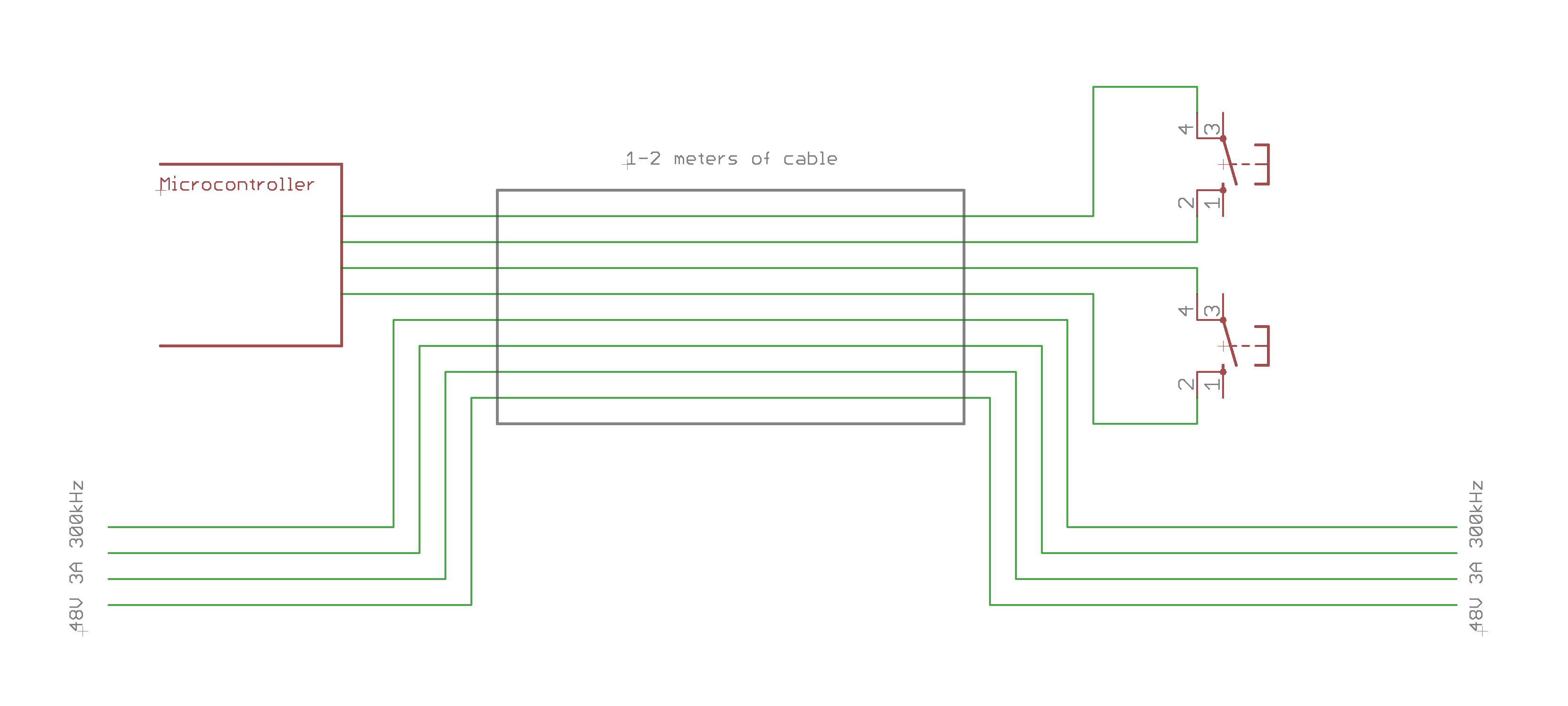
I'm currently working on redesigning the control circuit of a CNC machine (more specific: an Isel milling cutter). Only the digital part will be of interest, I'll keep the old power electronics (motor drivers and power supplies). Currently all parts of the circuitry are working well independent of each other, but when it comes to putting it all together, my circuit fails at several spots.
Measurements told me that this is mainly due to enormous EMI, crosstalk and other forms of electric noise, radiated from the power supply and some high-frequency, high-current traces going to the stepper motors.
In the second version of the PCB I want to solve all these (and some other) problems by making the circuit design as resistant to interference as possible.
What worries me the most are some DC signal lines that share the same physical cable with the motor's power lines (4x 48V 3A 300kHz stepping speed - the actual current frequency will be by far lower) for 1-2 meters outside the control box (see picture below).
What is the best practice to connect switch to the microcontroller running at 3.3V? Simply connect one side of the swicth to Vcc and the other to a pulldown resistor? I fear that using a voltage as low as 3 volts will make it more likely that errors might occur: just 1V of interference induced into the wire will make it hard for the microcontroller to distinguish between LOW and HIGH. Should I apply a higher voltage, let's say 24V (that's the way the original datasheet states the switches should be used)? But in that case, how should the level conversion be done? A voltage divider would scale the error just as the signal, wouldn't it?
As you can see, I'm a little lost here, any help is appreciated. Thank you in advance!
