What is the significance of the input and output impedance in a BJT circuit?
High output impedance means little to no current will flow at the output, why is this important?
What is the significance of the input and output impedance in a BJT circuit?
High output impedance means little to no current will flow at the output, why is this important?
The gain of an amplifier, a single device, depends on the GM, the dIout/dVin, also called transconductance. GM is a vacuum tube holdover, meaning conductance-mutual or how the input and output interact.
Knowing the GM, multiply that by the impedance at the output node, and you have the gain of that stage, of that single device.
But you must include ALL the resistances, all the impedances, hanging on the output node. That requires you know the Rload, the R_collector, the slope_of_the_collector_IV_curve, and the capacitive parasitics. All these in parallel affect the gain.
Should you implement a constant-current load on the collector, then the slope of the collector IV curve, described with the name of Early Voltage, or Vearly or just Va, will set the low frequency gain.
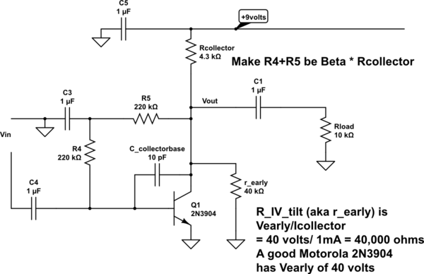
Here is a complete bipolar gain-stage, with a resistive Rcollector (not the constant-current load):

simulate this circuit – Schematic created using CircuitLab
What is the bandwidth of this circuit? The lower end is set by the capacitors. The upper end, the Tau, is the 10pF in parallel with Rcollector || R5 || r_early || Rload. If you build this, add 5 or 10pF more, for wiring capacitances. And a scope probe will add 10 ---20pF more. A quick number: 10pF + 4Kohm is 400 nanoSeconds Tau, or 2.5MegaRad/2*pi ~~ 0.4MHz F3dB.
Now, regarding input impedance, given voltage sources have some resistance or impedance, call it Zsource, the Zin of the bipolar will form a Voltage Divider with the Zsource. Darlington bipolars will greatly incread the Zin, and the voltage division becomes
Zsource / (Zsource + Zin)
Also notice the C_collectorbase, of value 10pF, which about right for a 2N3904. The collector end sees the 10pF; the base end sees 10pF * (1 * stage_gain), thus the base Zin (at high frequencies) suffers because of the signal charge being stolen by the C_collectorbase.
Notice the self-biasing, using 220,000 ohms in series, the total being BETA * Rcollector. This rather nicely sets the Vcollector at 4.5 volts +-, allowing a large "linear" swing. But you have to know the BETA rather accurately, if you want VDD/2 as the Qpoint. On the other hand, this method of biasing does give you a fine opamp (inverting input only) with over 100,000 Hz bandwidth. Note the 220,000 Rs do load both the Vin and the Vout.
It is not enough just to mention "BJT circuits" only.
There are BJT circuits which should have a large output resistance (current sources) and there are other circuits (voltage amplifiers) which should have a small output resistance. This is desired because we do not want that any load drastically will change the resistance that determines the gain.
Remember the opamp principle: High input resistance (MegOhm range) because the amplifier should not draw a large current (and cause unwanted voltage drops across the internal resistance of the signal source). The gain is determined by the feedback resistors only - and this gain depends not on the connected load because the output resuistance is extremely small.
In principle such a behaviour is wanted for simmple BJT amplifier stages also - however, this can be realized up to a certain degree only.
These specs such as gain, Zin, Zout, noise, slew rate, ... help other designer uses your design just as a module without knowing what is inside.
When you use many series of amplifiers, the output power, and voltage gain are highly related to Rin and Rout and loads.
In high-frequency circuits, you should match the impedance of load(impedance matching) and system for transferring the maximum power to load or antenna. (Rout of circuit is important)
For example, the best case for a system get voltage in the input and generate an output voltage(voltage_in voltage_out), the ideal case is infinite input impedance and zero output impedance. you should try to design with this criteria. It is not easy to generate such impedance, therefore the designer analyzes the Rin and Rout and writes in manual. Now, you design an ideal voltage amplifier with Rin in parallel with input, and Rout is placed in series with output.