2
\$\begingroup\$

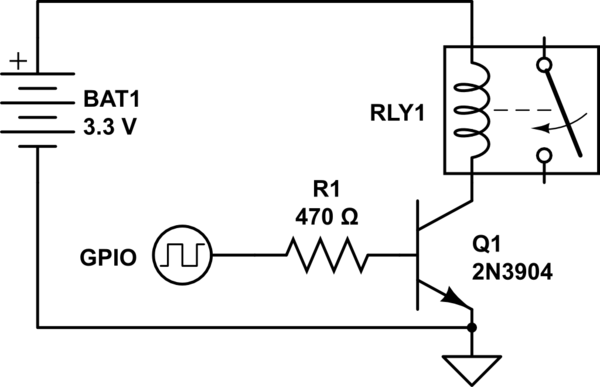
Given a low power signal relay, 3V 140mW coil, controlled by a 2n3904 npn transistor, is a flyback diode required? At what point is a flyback diode needed for any given inductor? Is it total power, voltage, current, henries?

schematic

simulate this circuit – Schematic created using CircuitLab

\$\endgroup\$
3
  • \$\begingroup\$ Did you try LTspice on this circuit? I got 11 kV spike if no diode is used, assuming on-off edges of 10 ns long (as per typica MCU GPIO switch). \$\endgroup\$ Commented Nov 22, 2018 at 9:23
  • \$\begingroup\$ @Ale..chenski A small signal transistor with breakdown voltage over 10kV doesn't look very realistic. \$\endgroup\$ Commented Nov 22, 2018 at 9:30
  • \$\begingroup\$ @DmitryGrigoryev, yes, and the interpretation of the simulation results should be that the circuit will fail without a flyback diode. Using 1N4148 fixes the problem to +4V spike, although I didn't calculate the dissipation. I assumed a 3.3V 25-Ohm relay with 90 mH inductance of the coil. \$\endgroup\$ Commented Nov 22, 2018 at 9:34

4 Answers 4

2
\$\begingroup\$

The appropriate rating would be the total energy required to damage a transistor. This is similar to ESD discharge, where typical rated energy is in microjoule range. Low current reed relays (with currents in single-digit or lower tens of mA) will actually qualify: a transistor designed to survive ESD shocks will survive the shocks from such a relay for some time.

It's still a pretty bad idea for a product subject to any kind of certification. Semiconductor devices are rarely certified to withstand repeated ESD abuse, and transistors often lack upper rating for breakdown voltage, which means that some devices will fail early, and others may experience voltage spikes in hundreds of V, giving you EMC problems or unexpected creepage issues.

\$\endgroup\$
2
\$\begingroup\$

When controlling inductive loads with semiconductor switches (transistors), the most dangerous for the devices is "flyback voltage" that is generated by an inductor when the switch gets turned OFF.

In theory the back-EMF voltage is determined by self-inductance and the rate of current change, as presented in layman terms:

enter image description here

VL = Ldi/dt

Therefore, the practical level of voltage spike depends on how fast your switch is. If you would use a mechanical on-off switch, when the switch impedance changes from milli-ohm (switch closed) to giga-ohm (switch open) in a fairly short time, the di/dt is infinitely high and the theoretical voltage spike is infinitely high. That's why electro-mechanical switches always "arching". And holding the inductor's wires might give you a sensible shock when disconnecting them from a battery. Therefore this flyback voltage can damage any silicon device. That's why the clamping diode is always a necessity. For engineering-level description, look at this Infinion appnote.

Technically you can reduce the di/dt using a very slow switch (with high breakdown voltage), and avoid the flyback diode, but slowing down the switch will likely cost much more than a diode.

ADDITION: Quick LTSpice simulation of the OP circuit produces a spike across the transistor with amplitude of 11 kV (!!!). This is under the typical GPIO edge rate of 10ns, and the relay parameters were assumed as 25 Ohm coil, 90 mH inductance.

If a N-FET 2N7002 used, the spike goes up to 7 kV. Slowing the switch time by using 100k (!) gate resistor R1 produces the switch time of about 100 ns and the spike amplitude of about 200V, which is still too high for a 60-V transistor.

However, using a 1N4148 diode across the relay coil eliminates all spikes to 4-V level.
\$\endgroup\$
2
  • \$\begingroup\$ 11kV or 7kV values are highly theoretical as any real transistor will be far into brakdown region and will clamp voltage to much lower value ( like 100V or so for 2n3904). Air can also break down from such a high voltages (is you manage to use really high-voltage transistors (3.3 kV are now avaiable) instead) 1mm airgap holds just about 3kV \$\endgroup\$ Commented Apr 24, 2022 at 6:02
  • \$\begingroup\$ @VolodymyrKalinyak, yes, this the entire point of the answer, interpretation of simulation results is that the circuit will fail without a flyback diode. The text explicitly says, if "switch time of about 100 ns and the spike amplitude of about 200V, which is still too high for a 60-V transistor." \$\endgroup\$ Commented Apr 24, 2022 at 23:11
-1
\$\begingroup\$
  1. Given a low power signal relay, 3V 140mW coil, controlled by a 2n3904 npn transistor, is a flyback diode required?

Yes, required.

  1. At what point is a flyback diode needed for any given inductor?

Every inductor, whatever its rating, is a energy storing device. While switching off we need to discharge it, for that we are going to use flyback diode. The diode should be selected based on the maximum operating voltage and current through the inductor.

  1. Is it total power, voltage, current, henries?

The flyback diode is to be selected based on voltage and current.

In your case, the coil voltage = 3V

power = 140mW

so current = 0.14/3 = 0.046 A

so you can select any general purpose diode. You can put an 1N4007 which is the most available and cheapest one.

\$\endgroup\$
1
  • \$\begingroup\$ not needed for every inductor, eg: with emitter follower drive the transistor turns off slowly. also 1n4148 is cheaper than 1N4007 and SF100 etc. \$\endgroup\$ Commented Nov 22, 2018 at 18:06
-1
\$\begingroup\$

They are needed when too much voltage is developed

How much voltage is your circuit developing when the transistor turns off, it it enough to damage the circuit or disrupt other circuits.

personally I'd fit a 1N4148 (or some other small diode) and avoid all the worry.

\$\endgroup\$

Your Answer

By clicking “Post Your Answer”, you agree to our terms of service and acknowledge you have read our privacy policy.

Not the answer you're looking for? Browse other questions tagged or ask your own question.