0
\$\begingroup\$

I am designing a board which can be powered over USB and includes the use of a LiPo battery along with its charger circuit. When the USB is connected, it charges the battery as well as powers the microcontroller. When the USB is unplugged, the microcontroller is powered by the battery.

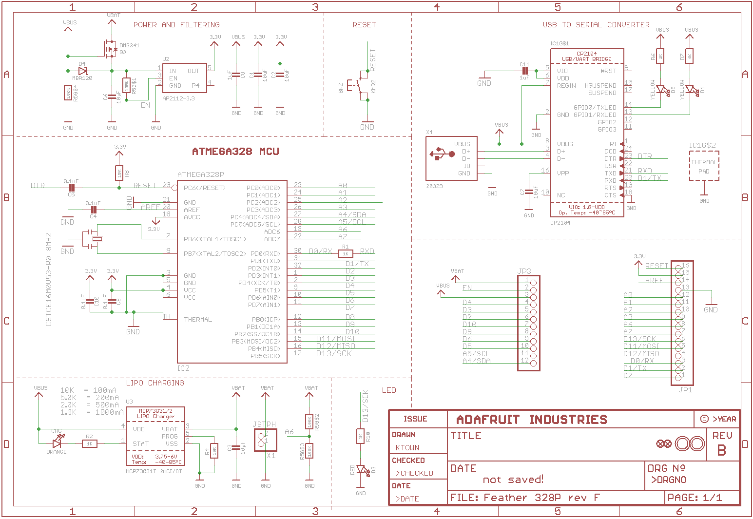
I was studying the Adafruit Feather boards as they incorporate this feature into their designs. They have implemented this in a couple different ways. The Feather 328P had a MOSFET and a diode such that when VBUS was present, it will override VBAT via the diode and when it wasn't power from the battery would flow through the MOSFET body diode:Feather 328P schematic
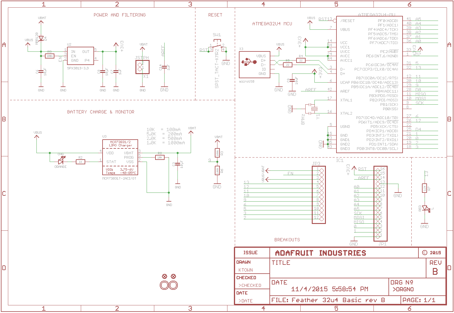
Then there is this variant, as present in the Feather 32u4 or the M0 boards where they put the diode across VBUS and VBAT with the anode on VBAT, and skip the MOSFET altogether:enter image description here
They both perform the same function but in seemingly different ways. What is the difference in the two implementations and what are the considerations for choosing one over the other?

\$\endgroup\$

1 Answer 1

2
\$\begingroup\$

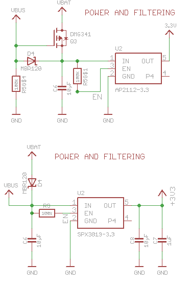
Compare the two schematics in detail at the relevant point: -

enter image description here

The top design uses a P channel MOSFET and, when the VBUS power is removed it will turn on that MOSFET and apply full battery voltage to the voltage regulator (U2).

The lower design uses a schottky diode in place of the MOSFET and so the battery voltage passed to U2 is somewhat lower (circa 0.25 volts to 0.3 volts) and so the circuit will fail to operate slightly earlier than the top design as the battery depletes.

\$\endgroup\$
4
  • \$\begingroup\$ So the tradeoff is between adding the component cost of a P-channel MOSFET and being able to extract a bit more life from the battery? Also, what purpose is the schottky diode serving in the top design? \$\endgroup\$
    – Ani
    Commented Nov 29, 2018 at 17:00
  • \$\begingroup\$ That's another trade-off. Firstly it has to be there or the MOSFET will never get its gate to ground and turn on when VBUS is removed. But, it adds a 0.25 - 0.3 volt-drop when VBUS is powering the circuit. That's not as big of a deal as dropping VBAT due to the diode forward voltage of course. \$\endgroup\$
    – Andy aka
    Commented Nov 29, 2018 at 17:06
  • \$\begingroup\$ Ah right that makes sense! I'm leaning towards implementing a circuit similar to the second design for my project but to be honest it's more just because it uses fewer components and less space. Would I be devaluing any electrical considerations (other than lower VBAT voltage) by going with this? \$\endgroup\$
    – Ani
    Commented Nov 29, 2018 at 17:32
  • 1
    \$\begingroup\$ I don't think so. The only loss is the battery voltage drop but if you are making a PCB why not populate for both options. \$\endgroup\$
    – Andy aka
    Commented Nov 29, 2018 at 18:30

Your Answer

By clicking “Post Your Answer”, you agree to our terms of service and acknowledge you have read our privacy policy.

Not the answer you're looking for? Browse other questions tagged or ask your own question.