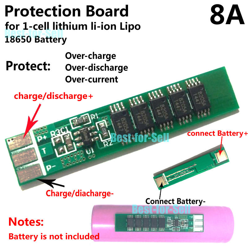
How this circuit to protect so call "over discharge"? since there's no output + and - terminals on the board and this case the load should connect directly to B+ and B- without any protection for discharging.
CUUSINHVIEN

-
\$\begingroup\$ ”load should connect directly to B+ and B- without any protection for discharging” No, it shouldn’t. \$\endgroup\$– winnyCommented Jan 15, 2019 at 7:12
2 Answers
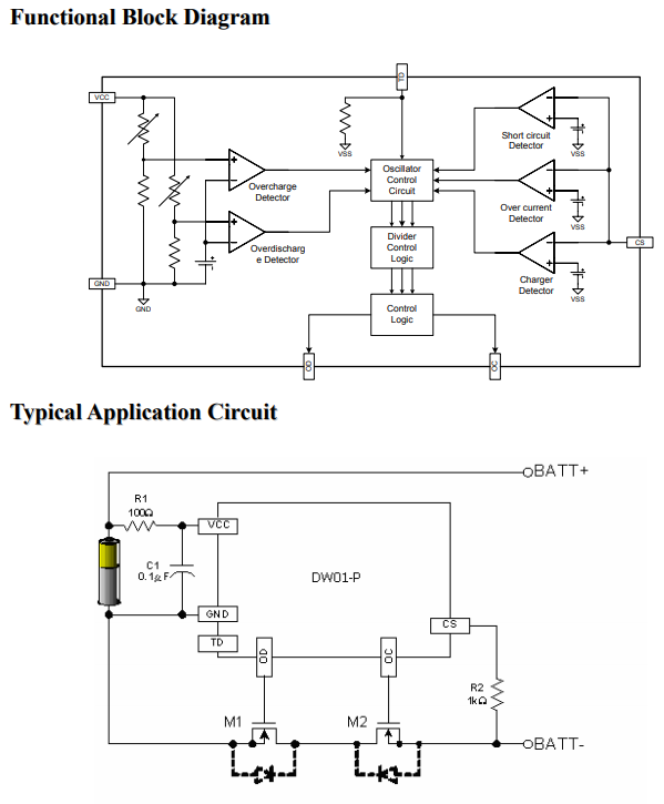
That board looks like a DW01 IC based board. Let's look at the DW01 datasheet.
It has these diagrams:
Note that the BATT+ and BATT- connections in this schematic correspond to the terminals marked P+ and P- on your PCB!
Also note that the IC detects Overdischarge by monitoring the voltage of the battery using the botton left comparator in the Functional Block diagram.
If the battery's voltage gets too low, the DW01 will switch off the two MOSFETs (M1 and M2) to open the connection to BATT- (= P- on your board) to stop the discharging.
I see five terminals on that board. The battery is connected to Battery+ and Battery-. I suspect that the load or charger is connected to P+ and P-. I have no idea what T is. Charge / discharge protection is wired between the battery and the other terminals.
I also expect, by the standard of the graphics, that there is no datasheet available for this device so you will have no detailed specification, instructions for use or safety standard data.
As always, our advice is, "No datasheet? No sale!"
-
\$\begingroup\$ "T" is usually for a thermistor, as an input to a charger, so it will stop charging or shut down the load if battery gets too hot. Typical is 10k to ground. \$\endgroup\$ Commented Jan 15, 2019 at 7:57

