4
\$\begingroup\$

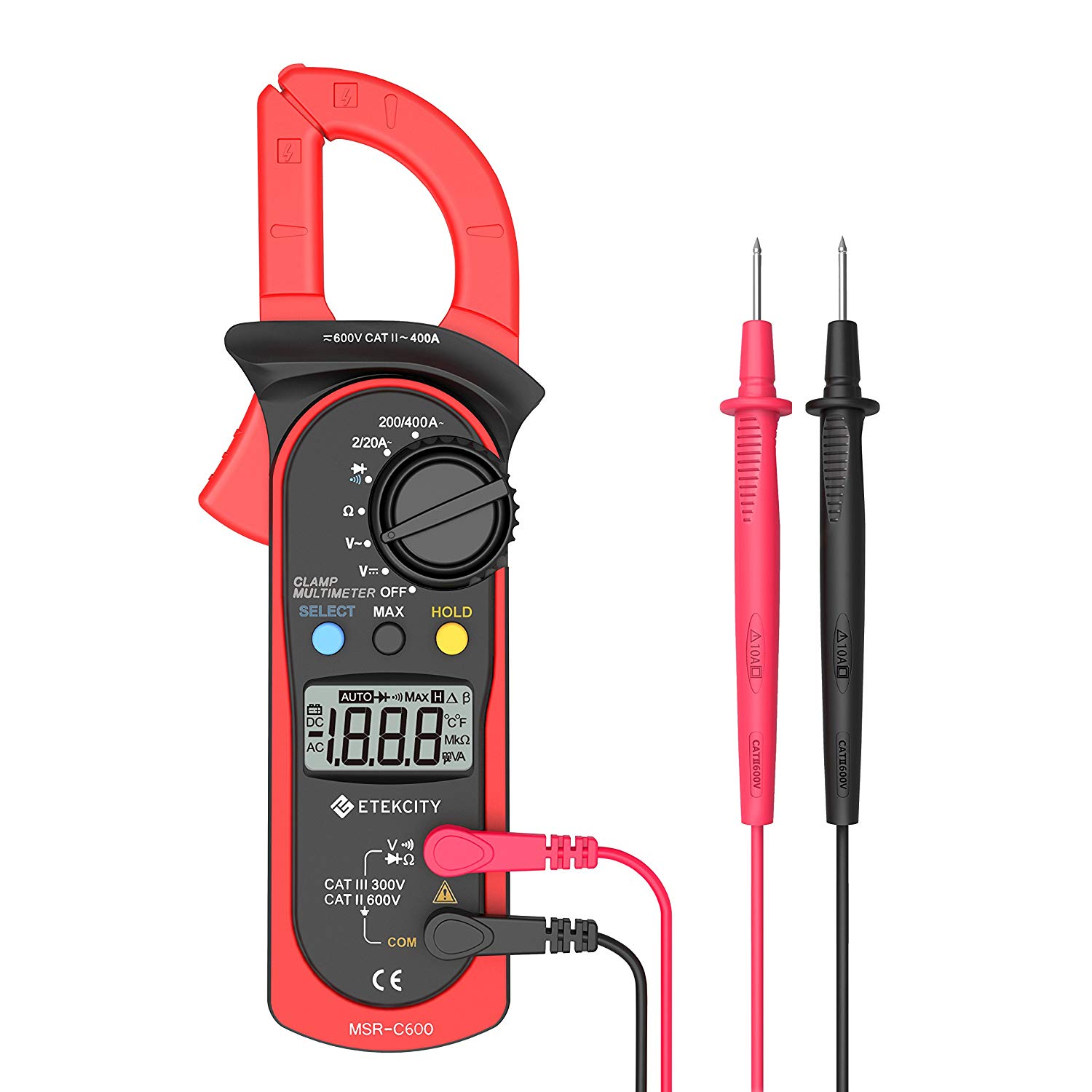
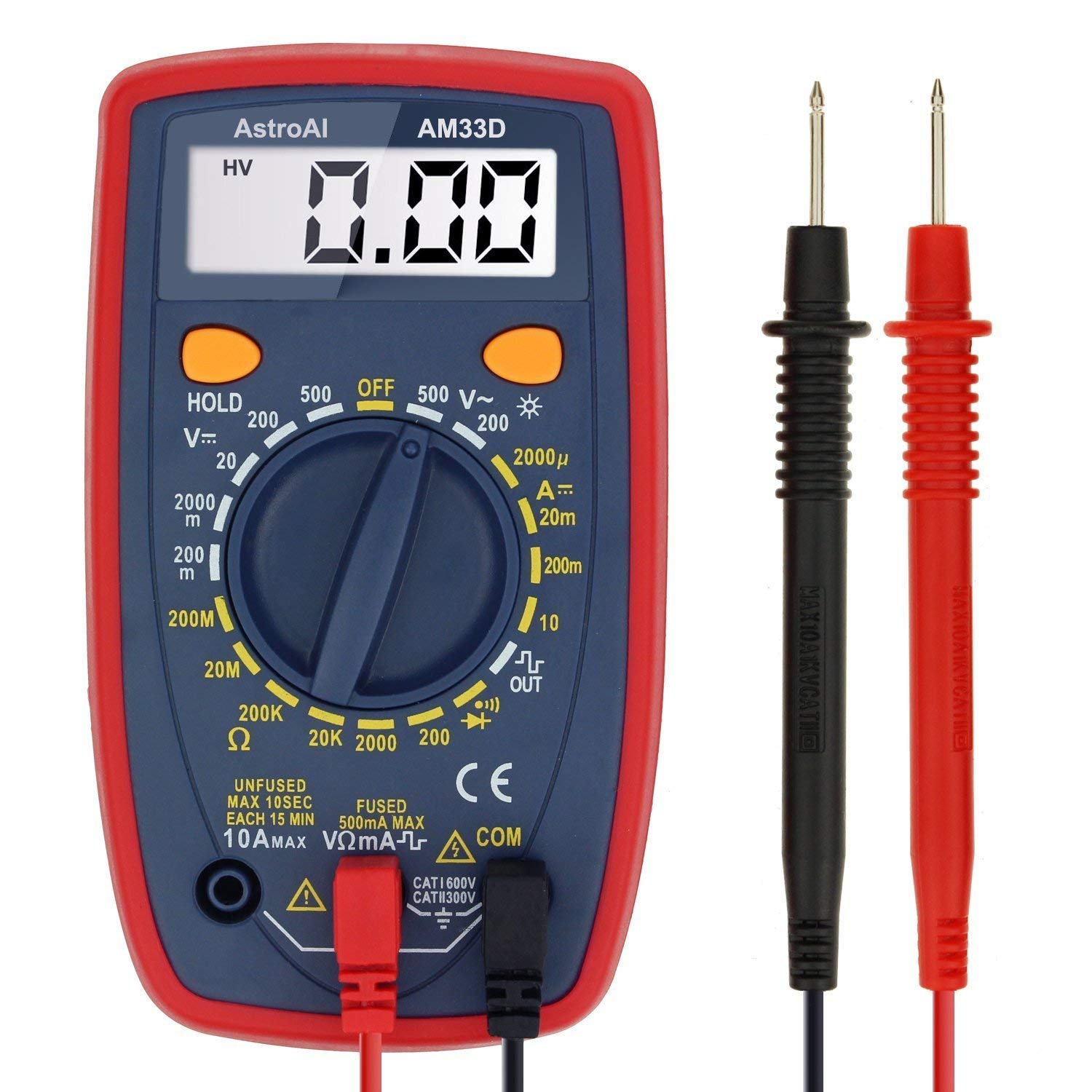
I have a multimeter in my toolbox that has ranges of values it measures in dc voltage, a lot like the one below which can read DC but reads it by orders of magnitude. In order to get a proper reading I have to select the correct range, otherwise my meter reads 0.00L.

enter image description here

I was browsing some tools on amazon and found this meter which, excepting amperage, does not need to have a range selected discretely. I was curious, it's obviously possible to do as this meter exists -- so why do your regular off-the-shelf wal-meters require you to select the value range?

enter image description here

\$\endgroup\$
2
  • 2
    \$\begingroup\$ Tools and devices differ in their complexity and cost. Like anything else. You have self-driving cars today - why not all of the cars then? \$\endgroup\$
    – Eugene Sh.
    Commented Jan 21, 2019 at 16:10
  • 2
    \$\begingroup\$ Note: The top manual range meter is $10, and the bottom auto ranging clamp meter is $27. Obviously these are both on the "budget" range for meters, but it shows just how inexpensive the manual meter is. Every cent counts in that part of the market. \$\endgroup\$
    – JPhi1618
    Commented Jan 21, 2019 at 19:53

3 Answers 3

10
\$\begingroup\$

The ones that don't require you to set a range have a feature called "auto-ranging". It's a feature that makes the meter easier to use — especially in the field — but sometimes slower to settle on a reading. It adds a bit of complexity to the meter logic (and the user interface), which is why the cheapest meters don't have it.

\$\endgroup\$
5
  • 3
    \$\begingroup\$ +1 As an aside, just because the meter doesn't appear to have range settings you (@Sidney) can't assume that it is autoranging. It may be that the meter really has just one range. \$\endgroup\$ Commented Jan 21, 2019 at 16:29
  • 5
    \$\begingroup\$ "easier to use"? Sometimes autoranging gets stuck in a cycle doing alternating readings on adjacent ranges. Especially ohmmeters. PITA. Having discretely selectable ranges turns off autoranging, allowing a stable display. This option is worthwhile having. Pure autoranging with no discrete scale ranges on the selector switch (2nd photo of OP's) is the low-cost method now, for a modern meter. \$\endgroup\$
    – glen_geek
    Commented Jan 21, 2019 at 16:53
  • 2
    \$\begingroup\$ @glen_geek Most meters I've used allow you to turn off the auto-ranging. It's a little inconvenient because you then need to use buttons to step up and down ranges, but autoranging getting stuck is uncommon enough that it's never been that big of a problem in my experience. \$\endgroup\$
    – Hearth
    Commented Jan 21, 2019 at 17:33
  • \$\begingroup\$ @Hearth Good point...OP's second photo shows a yellow HOLD push button. It likely means "hold-the-current reading" rather than "hold-the-current-range". I'd prefer the latter. Autoranging can be annoyingly slow sometimes. The blue SELECT apparently chooses between continuity-check and diode-test.(it isn't a range select). \$\endgroup\$
    – glen_geek
    Commented Jan 21, 2019 at 17:58
  • 1
    \$\begingroup\$ I have an auto-ranging meter with a button that cycles through the ranges. It is definitely useful to turn off auto-ranging when e.g. you're measuring a (slow) 5V square wave as the meter won't hunt for the range every time the voltage changes. \$\endgroup\$ Commented Jan 21, 2019 at 22:41
2
\$\begingroup\$

Many meters work by converting an input into a small voltage or current and then measuring that. There are a number of approaches meters can use to control their input range, which may be used individually or combined:

  1. Use a constant ratio of input signal to measured signal, and vary the relationship between the measured signal and the display. For example, a meter could scale an input scale by 1000:1, and then display the input scaled so that full-scale voltage is 400mV, 40mV, or 4mV. Such an approach used in isolation will generally limit a meter's useful dynamic range, since 0.1mV of noise would show up as 0.1V of noise in the measured value. Not a problem if the signal being measured is 300V, but very bad if the signal of interest is only 0.3V.

  2. Have several inputs to the measurement circuitry, which receive differently-divided inputs that are always fed to all of them. Have the measurement circuitry select whichever input is using a divide ratio appropriate to the signal being measured. This approach could be combined with the above approach by having inputs with 1000:1 and 10:1 dividers and then displaying the result scaled to show a full-scale voltage of 400mV or 40mV. Inputs over 4 volts would be read as above using the 1000:1 divider, but smaller inputs could use the input from the 10:1 divider, thus reducing 100-fold the effect of noise in the measurement circuitry.

  3. Change the ratio of input value to the voltage that appears at the measurement input.

Note that if a device is only measuring input voltage, approaches #1 and #2 are adequate if used together, since the meter will have little effect on the device or circuit being measured. When measuring resistance or current, however, the meter will need to affect the device under test, and there are trade-offs between accuracy and the amount of effect on the device being tested. One could theoretically measure any resistance by putting one milliamp through it and measuring the voltage, but getting an measurement that's accurate to 1% with a one ohm resistor would require measuring voltage accurate to 0.01mV--rather a tall order. On the flip side, measuring a one meg resistor using a 1mA current would require that one feed a watt into it, which would both be difficult for a meter to do, and might adversely affect the resistor being tested even if one could do it. Adjusting the measurement range for resistance and current is more easily accomplished by adjusting the effect of the measurement on the device under test so that it will produce a voltage in a certain range, but doing that may be more difficult than merely selecting an input. When sensing resistance, having a current source that can be switched under processor control between e.g. 0.1mA and 10mA may not be difficult, but changing the sense resistor when measuring current will generally be impractical.

A meter which uses a rotary switch to select input range can easily adjust how it measures things in whatever way is most convenient. A meter which selects ranges electronically may have more limited options.

\$\endgroup\$
0
\$\begingroup\$

A cheap ADC can give you 3 or so usable digits, after that the cost tends to go up significantly with each additional digit of precision. Moving coil meters were even worse in this regard.

So multimeters have "ranges", usually seperated by a factor of 10. Changing between ranges reconfigures the amplifiers/attenuators in the meter so the range of measurement is suited to the task at hand. For example if the ADC had a 2V range, then the 600V range would have a 300x* attenuation, the 200V range would have a 100x attenuation, the 20V range would have a 10x attenuation, the 2V range would have no attenuation.

Switching ranges electronically is possible, but it's not exactly trivial, the voltages involved are fairly high and multimeters must be tolerant of surge voltages substantially in excess of their nominal input voltage range. A mechanical switch is simpler, so is what is seen on bottom of the range multimeters.

Higher-end multimeters tend to default to an "autoranging" mode, where the range is selected electronically and automatically. This is convinient most of the time, but can be annoying when signals are repeatedly changing as the multimeter keeps changing ranges. So most better multimeters offer a way to override the autoranging and manually select a range.

\$\endgroup\$

Your Answer

By clicking “Post Your Answer”, you agree to our terms of service and acknowledge you have read our privacy policy.

Not the answer you're looking for? Browse other questions tagged or ask your own question.