0
\$\begingroup\$

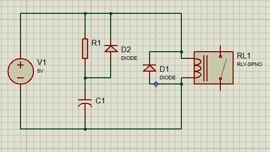
Check schematic below, On power on, I want to create a delay when the relay turns on of about 20 seconds. Once its on, it stays on until the power is cut. Timing accuracy is not important. Now I could use a 555 timer, but then I would need a transistor as well. That's two extra components. So I thought of just using a simple RC circuit in parallel with the relay as shown below.

About the flywheel diode (D1), I think it wont be needed since the capacitor will supply the di/dt at power turn off ?

I also added diode D2 to discharge the capacitor faster at turn off

Schematic

\$\endgroup\$
4
  • 2
    \$\begingroup\$ This won't work, the resistance that drives the capacitor only makes so that the capacitor is charged slowly, but the the relay will still activate immediately. It might delay the deactivation of the relay, but that's it. The 555 solution is well tested and you can find it as pre-assembled PCB from the usual chinese vendors, or eBay. \$\endgroup\$
    – Elmesito
    Commented Feb 28, 2019 at 17:05
  • \$\begingroup\$ @Elmesito, Isn't that slowly rising voltage what the relay sees since its connected in parallel to the capacitor ? \$\endgroup\$
    – Deadshot
    Commented Feb 28, 2019 at 17:12
  • 1
    \$\begingroup\$ Assuming that when you apply power to the circuit the capacitor is a short, then you will have two loads, the resistor R1 and the relay. The resistor is likely to have a resistance which is higher than the one of the relay, and therefore the relay will always receive a voltage higher than the one of the capacitor. \$\endgroup\$
    – Elmesito
    Commented Feb 28, 2019 at 17:16
  • \$\begingroup\$ @Elmesito, Oh I see, so I basically have to remove R1, but what if I connected the relay directly across the capacitor with R1 still there. Initially the resistor would drop 5V but eventually the capacitor would catch up ?, but then I guess the current for the relay would be too low since its connected in series with R1 ? \$\endgroup\$
    – Deadshot
    Commented Feb 28, 2019 at 17:36

2 Answers 2

1
\$\begingroup\$

To get the relay to delay start as you want, you need to have it connected across the capacitor in your diagram.

As you say, the freewheeling diode then becomes irrelevant. To get the relay to switch, the resistance used to charge the caps needs to be low enough that the equilibrium point eventually reached is high enough to put enough current into the relay coil to close. That then determines the size of the (bank of ) capacitor(s) you need for the appropriate timing. D2 also becomes irrelevant, since there's no path for it to discharge through, the relay coil current is the only thing that discharges the cap.

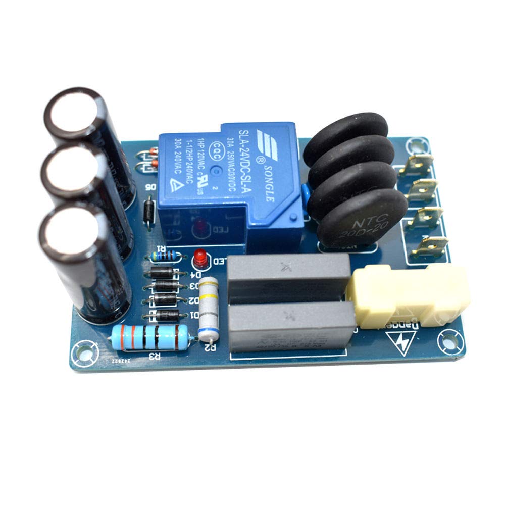
I have a few soft start boards (used with big SMPS and toroidal transformers) that work like this, the bulk and cost of the caps (on the left) means that a simple circuit with a low current charging cap and a transistor driving the relay would probably be a better choice.

enter image description here

\$\endgroup\$
4
  • \$\begingroup\$ Yeah, that's what I thought. I think the best option is to connect a MOSFET across the capacitor. Would I have to configure the timing based on Vth (threshold voltage) of the MOSFET ? \$\endgroup\$
    – Deadshot
    Commented Feb 28, 2019 at 18:02
  • 1
    \$\begingroup\$ Vth would be the trigger point, but allowing the gate voltage to slowly rise would produce a lot of heat in the FET as it conducts current with Vds still high. If the FET is big enough that won't matter, but you can add another transistor to make the action more snappy. See Fig 5 here - sound.whsites.net/articles/soft-start.htm \$\endgroup\$
    – Phil G
    Commented Feb 28, 2019 at 19:24
  • \$\begingroup\$ I looked at the IRLZ44N, looks like its still good for about 1 to 1.5 amps at a Vgs of 2.25 V. If the relay only draws about 70 mA, that should be good enough I think ? vishay.com/docs/91328/91328.pdf \$\endgroup\$
    – Deadshot
    Commented Feb 28, 2019 at 20:39
  • \$\begingroup\$ That has plenty of margin for this use, but with Vth being as low as 1V the cap is going to need to charge very slowly for a 20s delay, so it's still going to be fairly slow to get through the transition. Now you've got a transistor in the circuit, I'd be tempted to use some sort of timer rather than an RC circuit to switchi it on. A PIC10 or ATtiny could do this with no external components other than a regulator. Under $1 in components, and you could use a cheaper FET if you're switching it on cleanly. \$\endgroup\$
    – Phil G
    Commented Mar 1, 2019 at 16:28
0
\$\begingroup\$

I have used a resistor and capacitor across the relay coil. You will also get a slow release but that can be eliminated by feeding the capacitor via one or the relay back contacts.

\$\endgroup\$

Your Answer

By clicking “Post Your Answer”, you agree to our terms of service and acknowledge you have read our privacy policy.

Not the answer you're looking for? Browse other questions tagged or ask your own question.