0
\$\begingroup\$

I'm looking to build a supervisory circuit which monitors a single voltage rail. When the monitored rail goes from HIGH to LOW, the supervisory IC asserts an interrupt signal to the system MCU to allow it to power down. The MCU can then assert a kill command to the supervisory IC, which turns off the enable output.

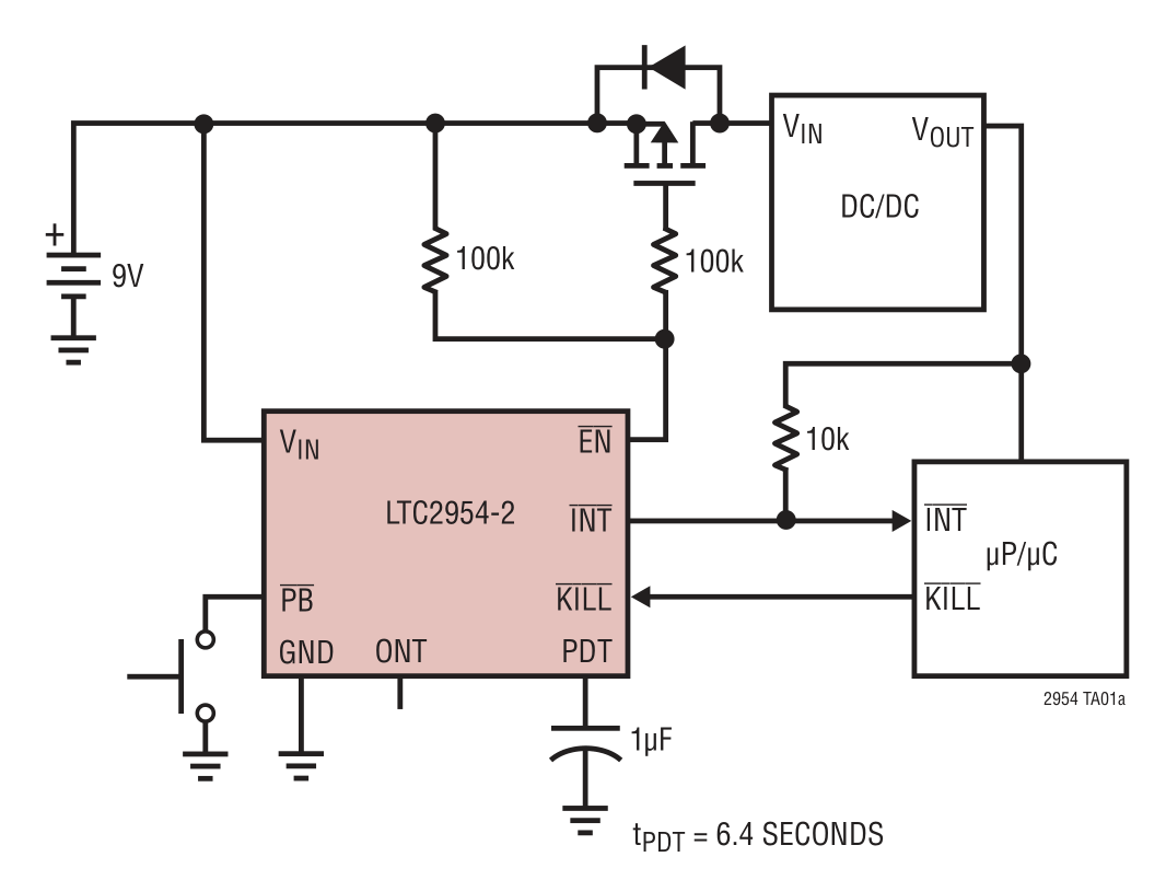
Unfortunately the only suitable ICs I have come across thus far have been for pushbutton input, which isn't suitable for my use case, as the monitored input is a static voltage rather than a momentary pulse. The following schematic for the LTC2954 offers the exact functionality I'm after, if the pushbutton input (PB) were replaced with a static voltage monitor input. Note the adjustable power down timer (PDT) which can be used as a back up in case the MCU never asserts the kill command.

enter image description here

Can anyone recommend a suitable IC or family of ICs? There's any number of similar pushbutton ICs, as well as a range of watchdog timer and reset-based voltage monitoring ICs, but I'm struggling to find an IC which provides the described functionality for non-pushbutton input.

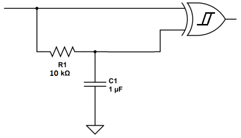
EDIT: How about using a schmitt trigger XOR circuit to simulate a pushbutton press when the state of the monitored rail changes (taken from this post):

enter image description here

If my understanding is correct, I could then utilise a standard pushbutton controller IC with a non-pushbutton input?

\$\endgroup\$
3
  • \$\begingroup\$ Have you looked into using a comparator or brown-out detector IC with an open collector/open-drain output, as an option for an IC that can drive the pushbutton pin in the same way as the pictured pushbutton? \$\endgroup\$
    – nanofarad
    Commented Mar 8, 2019 at 21:36
  • \$\begingroup\$ I haven't, how exactly would that work? I'd utilise the pushbutton circuitry as above, but emulate a pushbutton pulse from a steady-state voltage input? \$\endgroup\$
    – jars121
    Commented Mar 8, 2019 at 21:39
  • 2
    \$\begingroup\$ Look into power monitor IC's by Maxim. \$\endgroup\$
    – user105652
    Commented Mar 8, 2019 at 22:05

1 Answer 1

1
\$\begingroup\$

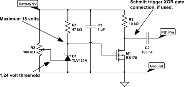
This simple design might work just fine. The TLV431A is a 3 pin adjustable zener with a 1.25 volt ref, but in this design it is used as a comparator. Combined with a 100K variable resistor it can be set to trip from 1.25 volts up to the battery voltage. This IC is very stable. The N-channel MOSFET is a level shifter/inverter. The 47K resistor sets the minimum drive current for the TLV431, and under a low voltage trip condition the MOSFET gate goes up to the battery voltage, so it is ON enough for the drain pin to ground the PB\ input of your controller IC.

Adjust the battery voltage (adjustable supply or dropping diodes) to a low value that you want the power to be cut off, then adjust R2 until the circuit triggers a shutdown by pulling the PB\ pin low. Now it is ready to use. It has been modified so the 'low' signal to the PB pin is just a brief pulse. When battery voltage returns to normal the MOSFET shuts OFF.

If an ON and OFF pulse is needed add a Schmitt trigger XOR gate from the CD4000 series of logic, along with the RC time delay.

schematic

simulate this circuit – Schematic created using CircuitLab

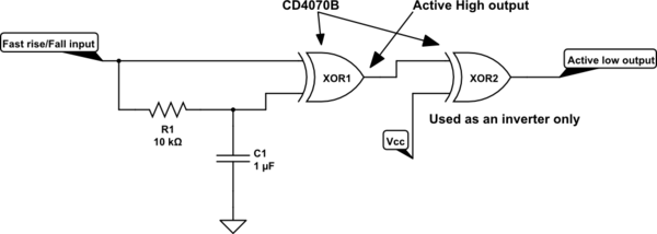
This is the correct schematic for a output normally high, or logic '1'. Any change in the input causes a brief low pulse at the output.The MOSFET turning on or off will create a positive pulse at the first XOR gate output, so another XOR gate is used as an inverter to get a brief negative pulse. There are 4 gates per package. Unused inputs MUST be grounded.

schematic

simulate this circuit

\$\endgroup\$
4
  • \$\begingroup\$ Good answer.... \$\endgroup\$
    – D.A.S.
    Commented Mar 8, 2019 at 22:56
  • \$\begingroup\$ To confirm, this circuit will produce a pulse (the width of which is given by the RC timing circuit?) both when the voltage drops below the threshold as well as when the voltage rises above the threshold? \$\endgroup\$
    – jars121
    Commented Mar 8, 2019 at 23:01
  • \$\begingroup\$ It does not have a pulse output, though a 100nF capacitor to the PB pin would allow a brief low pulse when battery drops below a set threshold. When voltage is normal again it shuts OFF the MOSFET. There is no ON pulse. \$\endgroup\$
    – user105652
    Commented Mar 8, 2019 at 23:18
  • \$\begingroup\$ If you need a negative pulse for both ON and OFF conditions you could add the above schmitt trigger XOR gate directly to the MOSFET drain pin. As it goes either HIgh or Low a pulse will be generated. Use CD4000 series logic, which will work from 3 volts to 15 volts. \$\endgroup\$
    – user105652
    Commented Mar 8, 2019 at 23:30

Your Answer

By clicking “Post Your Answer”, you agree to our terms of service and acknowledge you have read our privacy policy.

Not the answer you're looking for? Browse other questions tagged or ask your own question.