0
\$\begingroup\$

I've been scratching my head for a few days over getting the NRF24L01+ modules to work on AVRs (ATMega328/p). I followed Gizmosnack's tutorial, not changing very much at all from his code. I've also tried a couple libraries but some didn't compile, some compiled but didn't work. I read quite a few Stackexchange posts as well but none seem to help.

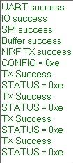
I've got UART debugging going on, and the transmitter shows this:

tx

Which claims TX success, but I'm skeptical since the IRQ pin doesn't show any activity even though those CONFIG bits shouldn't be masking the TX_DS interrupt.

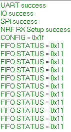
The receiver shows this:

rx

Which claims both FIFOs are empty, which seems correct. So I'm able to communicate with each NRF over SPI just fine, but I've gotten no semblance of wireless communication working.

Both Atmel Studio projects have F_CPU as a Defined Symbol (F_CPU = 8000000UL)

Transmitter Code

#include <avr/io.h>
#include <stdio.h>
#include <util/delay.h>
#include <avr/interrupt.h>

#include "nrf24l01.h"
#include "my_usartlib.h"

void initSPI();
uint8_t writeByteSPI(uint8_t);
uint8_t readReg(uint8_t);
void writeReg(uint8_t, uint8_t);
uint8_t *readRegArray(uint8_t, uint8_t *data, uint8_t);
void nrf24l01_init();
void nrf_transmit(uint8_t * W_buff);
void reset_IRQ();


uint8_t rx_address[] = {0x12, 0x12, 0x12, 0x12, 0x12};
uint8_t tx_address[] = {0x12, 0x12, 0x12, 0x12, 0x12};

volatile uint8_t tx_flag = 0x00;
uint8_t tx_buffer[5]; 

int main(void){

    usart_init();
    usart_tx_string("UART success\n");

    DDRD |= (1<<6);     //D6 (LED) input
    DDRD &= ~(1<<2);    //D2 (INT0) input
    usart_tx_string("IO success\n");

    initSPI();
    usart_tx_string("SPI success\n");

    for(int i = 0; i < 5; i++){
        tx_buffer[i] = 2*i;
    }
    usart_tx_string("Buffer success\n");
    nrf24l01_init();
    usart_tx_string("NRF TX success\n");

    PORTD |= (1<<6);
    _delay_ms(500);
    PORTD &= ~(1<<6);
    _delay_ms(500);     //flash LED to denote success

    EICRA |= (1<<ISC01);    //Falling edge detect
    EIMSK |= (1<<INT0);

    tx_buffer[0] = 0x10;
    tx_buffer[1] = 0x20;
    tx_buffer[2] = 0x30;

    usart_tx_string("CONFIG = 0x");
    usart_tx_val(readReg(CONFIG), 16); usart_tx('\n');

    sei();
    while (1) {
        _delay_ms(2000);
        nrf_transmit(tx_buffer);

        if((readReg(STATUS) & (1<<4)) != 0){
            usart_tx_string("TX Failure\n");
        } else{
            usart_tx_string("TX Success\n");
        }

        usart_tx_string("STATUS = 0x");
        usart_tx_val(readReg(STATUS), 16); usart_tx('\n');
        reset_IRQ();
    }
}

void initSPI(){
    DDRB |= (1<<DDB5) | (1<<DDB3) | (1<<DDB2) | (1<<DDB1);

    SPCR |= (1<<SPE) | (1<<MSTR);

    PORTB |= (1 << 2);  // CSN High
    PORTB &= ~(1 << 1); // CE low
}

uint8_t writeByteSPI(uint8_t cData){
    SPDR = cData;
    while(!(SPSR & (1<<SPIF)));
    return SPDR;
}

uint8_t readReg(uint8_t reg){
    _delay_us(10);
    PORTB &= ~(1 << 2);

    _delay_us(10);
    writeByteSPI(R_REGISTER + reg);

    _delay_us(10);  
    reg = writeByteSPI(NOP);

    _delay_us(10);
    PORTB |= (1 << 2);
    return reg;
}

void writeReg(uint8_t reg, uint8_t data){
    _delay_us(10);
    PORTB &= ~(1 << 2);

    _delay_us(10);
    writeByteSPI(W_REGISTER + reg);

    _delay_us(10);
    writeByteSPI(data);

    _delay_us(10);
    PORTB |= (1 << 2);  
}

void writeRegArray(uint8_t reg, uint8_t *data, uint8_t data_length){
    _delay_us(10);
    PORTB &= ~(1 << 2);
    _delay_us(10);
    writeByteSPI(W_REGISTER + reg);
    _delay_us(10);

    for(int i = 0; i < data_length; i++){
        writeByteSPI(data[i]);
        _delay_us(10);
    }

    PORTB |= (1 << 2);
}

uint8_t *readRegArray(uint8_t reg, uint8_t *data, uint8_t data_length){
    static uint8_t ret[32];

    _delay_us(10);
    PORTB &= ~(1 << 2);
    _delay_us(10);
    writeByteSPI(reg);
    _delay_us(10);

    for(int i = 0; i < data_length; i++){
        ret[i] = writeByteSPI(NOP);
        _delay_us(10);
    }

    PORTB |= (1 << 2);

    return ret;
}

void nrf24l01_init(){
    _delay_ms(100);

    writeReg(EN_AA, 0x01);      //enable auto-ack
    writeReg(SETUP_RETR, 0x2F); //15 retries at 750us for EN_AA

    writeReg(EN_RXADDR, 0x01);  //enable data pipe 0

    writeReg(SETUP_AW, 0x03);   //5 bytes of rx address

    writeReg(RF_CH, 0x01);      //2.401GHz frequency

    writeReg(RF_SETUP, 0x07);   //power and range modes

    writeRegArray(RX_ADDR_P0, rx_address, 5);
    writeRegArray(TX_ADDR, tx_address, 5);

    writeReg(RX_PW_P0, 5);  //5 byte payload width

    writeReg(CONFIG, 0x0E); //bits 3, 2, 1 (transmitter)
    _delay_ms(100);
}

void nrf_transmit(uint8_t * W_buff){
    writeRegArray(FLUSH_TX, W_buff, 0);
    writeRegArray(W_TX_PAYLOAD, W_buff, 5);

    _delay_ms(10);
    PORTB |= (1 << 1);  //CE high, transmit data
    _delay_us(20);      
    PORTB &= ~(1 << 1); //CE low, stop transmitting
    _delay_ms(10);

}

void reset_IRQ(void){
    writeReg(STATUS, 0x70);
}

ISR(INT0_vect){
    usart_tx_string("IRQ triggered\n");
}

Receiver Code

#include <avr/io.h>
#include <stdio.h>
#include <util/delay.h>
#include <avr/interrupt.h>

#include "nrf24l01.h"
#include "my_usartlib.h"

void initSPI();
uint8_t writeByteSPI(uint8_t);
uint8_t readReg(uint8_t);
void writeReg(uint8_t, uint8_t);
uint8_t *readRegArray(uint8_t, uint8_t *data, uint8_t);
void nrf24l01_init();
void nrf_transmit(uint8_t * W_buff);
void reset_IRQ();


uint8_t rx_address[] = {0x12, 0x12, 0x12, 0x12, 0x12};
uint8_t tx_address[] = {0x12, 0x12, 0x12, 0x12, 0x12};

uint8_t* rx_buffer;
volatile uint8_t rx_flag = 0x00;


int main(void){
    usart_init();
    usart_tx_string("UART success\n");

    DDRD |= (1<<6);     //D6 (LED) output
    DDRD &= ~(1<<2);    //D2 (INT0) input
    usart_tx_string("IO success\n");

    initSPI();
    usart_tx_string("SPI success\n");

    nrf24l01_init();
    usart_tx_string("NRF RX Setup success\n");

    _delay_ms(200);
    PORTD |= (1<<6);
    _delay_ms(200);
    PORTD &= ~(1<<6);
    _delay_ms(200);     //flash LED to denote success

    EICRA |= (1<<ISC01);    //Falling edge detect
    EIMSK |= (1<<INT0);


    usart_tx_string("CONFIG = 0x");
    usart_tx_val(readReg(CONFIG), 16); usart_tx('\n');
    sei();
    PORTB |= (1 << 1);  //CE high, start listening

    while (1) {
        if(rx_flag){
            PORTB &= ~(1<<1);       //stop listening
            rx_flag = 0x00;
            for(int i = 0; i < 5; i++){
                usart_tx_val(rx_buffer[i], 16);
                usart_tx(',');
            }
            usart_tx('\n');

            PORTD |= (1<<6);
            _delay_ms(2000);
            PORTD &= ~(1<<6);
            _delay_ms(2000);    //LED ON for 2s, wait for 2s

            PORTB |= (1<<1);    //start listening again
            reset_IRQ();    
        }
        _delay_ms(1000);
        usart_tx_string("FIFO STATUS = 0x");
        usart_tx_val(readReg(FIFO_STATUS), 16); usart_tx('\n');
    }
}


void initSPI(){
    DDRB |= (1<<DDB5) | (1<<DDB3) | (1<<DDB2) | (1<<DDB1);

    SPCR |= (1<<SPE) | (1<<MSTR);

    PORTB |= (1 << 2);  // CSN High
    PORTB &= ~(1 << 1); // CE low
}

uint8_t writeByteSPI(uint8_t cData){
    SPDR = cData;
    while(!(SPSR & (1<<SPIF)));
    return SPDR;
}

uint8_t readReg(uint8_t reg){
    _delay_us(10);
    PORTB &= ~(1 << 2);

    _delay_us(10);
    writeByteSPI(R_REGISTER + reg);

    _delay_us(10);
    reg = writeByteSPI(NOP);

    _delay_us(10);
    PORTB |= (1 << 2);
    return reg;
}

void writeReg(uint8_t reg, uint8_t data){
    _delay_us(10);
    PORTB &= ~(1 << 2);

    _delay_us(10);
    writeByteSPI(W_REGISTER + reg);

    _delay_us(10);
    writeByteSPI(data);

    _delay_us(10);
    PORTB |= (1 << 2);
}

void writeRegArray(uint8_t reg, uint8_t *data, uint8_t data_length){
    _delay_us(10);
    PORTB &= ~(1 << 2);
    _delay_us(10);
    writeByteSPI(W_REGISTER + reg);
    _delay_us(10);

    for(int i = 0; i < data_length; i++){
        writeByteSPI(data[i]);
        _delay_us(10);
    }

    PORTB |= (1 << 2);
}

uint8_t *readRegArray(uint8_t reg, uint8_t *data, uint8_t data_length){
    static uint8_t ret[32];

    _delay_us(10);
    PORTB &= ~(1 << 2);
    _delay_us(10);
    writeByteSPI(reg);
    _delay_us(10);

    for(int i = 0; i < data_length; i++){
        ret[i] = writeByteSPI(NOP);
        _delay_us(10);
    }

    PORTB |= (1 << 2);

    return ret;
}

void nrf24l01_init(){
    _delay_ms(100);

    writeReg(EN_AA, 0x01);      //enable auto-ack
    writeReg(SETUP_RETR, 0x2F); //15 retries at 750us for EN_AA

    writeReg(EN_RXADDR, 0x01);  //enable data pipe 0

    writeReg(SETUP_AW, 0x03);   //5 bytes of rx address

    writeReg(RF_CH, 0x01);      //2.401GHz frequency

    writeReg(RF_SETUP, 0x07);   //power and range modes

    writeRegArray(RX_ADDR_P0, rx_address, 5);
    writeRegArray(TX_ADDR, tx_address, 5);

    writeReg(RX_PW_P0, 5);  //5 byte payload width

    writeReg(CONFIG, 0x1F); //bits 4, 3, 2, 1, 0 (receiver)
    _delay_ms(100);
}

void reset_IRQ(void){
    writeReg(STATUS, 0x70);
}

ISR(INT0_vect){
    PORTB &= ~(1 << 1);
    rx_buffer = readRegArray(R_RX_PAYLOAD, rx_buffer, 5);
    rx_flag = 0xFF;

    reset_IRQ();
}   

Hardware

I've got them connected up to 3.3V Arduino Pro Mini's, one powered with a CP2102 module with the 3.3V trace problem fixed (I've cut the trace, oscilloscope confirms 3.299V on average under load) and the other with an STLink V2 USB Dongle (it was the only other easy 3.3V source around)

I've confirmed on an oscilloscope that the IRQ pin doesn't change. Pin connections are all just on a breadboard, LEDs (w/ 400ohms) on PD6 for each. I have a 100uF, 25V electrolytic capacitor on each power rail, and I didn't notice any significant voltage dips on the oscilloscope.

Fuses read E2 D9 07 (brownout disabled, 8Mhz internal)

I'm quite lost here, so any help is appreciated

\$\endgroup\$
4
  • \$\begingroup\$ You should probably try using some examples unchanged, also if your hardware can do it, perhaps (temporarily, only as a test) some from Arduino land. Most users don't bother with the IRQ signal. Are you using hardware CE? (CS is a distinct signal from CS) . If you have boards that have a power amplifier on them (2nd chip, typically also an SMA antenna connection) you probably need to control that as well. \$\endgroup\$ Commented Mar 13, 2019 at 21:37
  • \$\begingroup\$ For the libraries, they were unchanged. As for Gizmosnack's, his actually isn't all-inclusive and some changes were necessary to create the receiver code, which compiled but exhibited the same issues. If I understand your question right, I've got CSN on PB5 and CE on PB1. It's just controlled manually by setting the PORTB bit, set before and after the AVR's SPI hardware takes control. No PA on my NRF boards either, just the simple 8-pin breakout boards \$\endgroup\$
    – Orotavia
    Commented Mar 13, 2019 at 21:58
  • 1
    \$\begingroup\$ Seems to be some inconsistency about the CSN pin between your downs and code. Also trying to send serial messages from an ISR tends to be a bad idea. \$\endgroup\$ Commented Mar 13, 2019 at 22:05
  • \$\begingroup\$ Oh, that was a typo my bad. Don't think I can edit comments yet. CSN is PB2, CE on PB1. Just checked my wiring to confirm that. I'll swap the UART out for an LED flash in the TX code too, thanks. \$\endgroup\$
    – Orotavia
    Commented Mar 13, 2019 at 22:09

1 Answer 1

0
\$\begingroup\$

So I had a few issues and frankly I lost track of which fix did what. For anyone who stumbles on this solution, I'll throw my new code here. I switched to Pipe 1 (I think Pipe 0 is used for the auto-ACK?) and fixed my TX buffer, since my original didn't actually write anything into it. At some point I switched up the data-rates, so make sure you keep all your addresses, data-rates, and frequencies synced between the PTX and PRX.

TX

#include <avr/io.h>
#include <stdio.h>
#include <util/delay.h>
#include <avr/interrupt.h>

#include "nrf24l01.h"
#include "my_usartlib.h"

void initSPI();
uint8_t writeByteSPI(uint8_t);
uint8_t readReg(uint8_t);
void writeReg(uint8_t, uint8_t);
uint8_t *readRegArray(uint8_t, uint8_t *data, uint8_t);
uint8_t *writeToTXBuffer(uint8_t *data, uint8_t data_length);
void nrf24l01_init();
void nrf_transmit(uint8_t * W_buff);
void reset_IRQ();


uint8_t rx_address[] = {0x12, 0x12, 0x12, 0x12, 0x12};
uint8_t tx_address[] = {0x12, 0x12, 0x12, 0x12, 0x12};

volatile uint8_t tx_flag = 0x00;
uint8_t tx_buffer[5]; 
uint8_t *dataRead;

int main(void){

    usart_init();

    DDRD |= (1<<6);     //D6 (LED) input
    DDRD &= ~(1<<2);    //D2 (INT0) input

    initSPI();

    for(int i = 0; i < 5; i++){
        tx_buffer[i] = 2*i;
    }

    nrf24l01_init();

    PORTD |= (1<<6);
    _delay_ms(500);
    PORTD &= ~(1<<6);
    _delay_ms(500);     //flash LED to denote success

    EICRA |= (1<<ISC01);    //Falling edge detect
    EIMSK |= (1<<INT0);

    usart_tx_string("CONFIG = 0x");
    usart_tx_val(readReg(CONFIG), 16); usart_tx('\n');

    sei();
    usart_tx_string("TX Init Success\n");

    while (1) {
        _delay_ms(2000);

        nrf_transmit(tx_buffer);
        _delay_ms(10);          // allow STATUS to update

        if((readReg(STATUS) & (1<<4)) != 0){
            usart_tx_string("TX Failure\n");
        } else{
            usart_tx_string("TX Success\n");
        }

        usart_tx_string("STATUS = 0x");
        usart_tx_val(readReg(STATUS), 16); usart_tx('\n');

        reset_IRQ();
    }
}

void initSPI(){
    DDRB |= (1<<DDB5) | (1<<DDB3) | (1<<DDB2) | (1<<DDB1);

    SPCR |= (1<<SPE) | (1<<MSTR);

    PORTB |= (1 << 2);  // CSN High
    PORTB &= ~(1 << 1); // CE low
}

uint8_t writeByteSPI(uint8_t cData){
    SPDR = cData;
    while(!(SPSR & (1<<SPIF)));
    return SPDR;
}

uint8_t readReg(uint8_t reg){
    _delay_us(10);
    PORTB &= ~(1 << 2);

    _delay_us(10);
    writeByteSPI(R_REGISTER + reg);

    _delay_us(10);  
    reg = writeByteSPI(NOP);

    _delay_us(10);
    PORTB |= (1 << 2);
    return reg;
}

void writeReg(uint8_t reg, uint8_t data){
    _delay_us(10);
    PORTB &= ~(1 << 2);

    _delay_us(10);
    writeByteSPI(W_REGISTER + reg);

    _delay_us(10);
    writeByteSPI(data);

    _delay_us(10);
    PORTB |= (1 << 2);  
}

void writeRegArray(uint8_t reg, uint8_t *data, uint8_t data_length){
    _delay_us(10);
    PORTB &= ~(1 << 2);
    _delay_us(10);
    writeByteSPI(W_REGISTER + reg);
    _delay_us(10);

    for(int i = 0; i < data_length; i++){
        writeByteSPI(data[i]);
        _delay_us(10);
    }

    PORTB |= (1 << 2);
}

uint8_t *readRegArray(uint8_t reg, uint8_t *data, uint8_t data_length){
    static uint8_t ret[32];

    _delay_us(10);
    PORTB &= ~(1 << 2);
    _delay_us(10);
    writeByteSPI(reg);
    _delay_us(10);

    for(int i = 0; i < data_length; i++){
        ret[i] = writeByteSPI(NOP);
        _delay_us(10);
    }

    PORTB |= (1 << 2);

    return ret;
}

uint8_t *writeToTXBuffer(uint8_t *data, uint8_t data_length){

    _delay_us(10);
    PORTB &= ~(1 << 2);
    _delay_us(10);
    writeByteSPI(W_TX_PAYLOAD);
    _delay_us(10);

    for(int i = 0; i < data_length; i++){
        writeByteSPI(data[i]);
        _delay_us(10);
    }

    PORTB |= (1 << 2);

    return data;
}

void nrf24l01_init(){
    _delay_ms(100);

    writeReg(EN_AA, 0x3F);      //enable auto-ack
    writeReg(SETUP_RETR, 0x2F); //15 retries at 750us for EN_AA

    writeReg(EN_RXADDR, 0x03);  //enable data pipe 0 & 1

    writeReg(SETUP_AW, 0x03);   //5 bytes of rx address

    writeReg(RF_CH, 0x01);      //2.401GHz frequency

    writeReg(RF_SETUP, 0x06);   //power and range modes

    writeRegArray(RX_ADDR_P0, tx_address, 5);
    writeRegArray(TX_ADDR, tx_address, 5);

    writeReg(RX_PW_P0, 5);  //5 byte payload width

    writeReg(CONFIG, 0x5E); //transmitter, TX_DS interrupt
    _delay_ms(100);
}

void nrf_transmit(uint8_t *W_buff){
    readRegArray(FLUSH_TX, W_buff, 0);
    //readRegArray(W_TX_PAYLOAD, W_buff, 5);
    writeToTXBuffer(W_buff, 5);

    usart_tx_string("FIFO STATUS = 0x");
    usart_tx_val(readReg(FIFO_STATUS), 16); usart_tx('\n');

    _delay_ms(10);
    PORTB |= (1 << 1);  //CE high, transmit data
    _delay_us(20);      
    PORTB &= ~(1 << 1); //CE low, stop transmitting
    _delay_ms(10);

}

void reset_IRQ(void){
    writeReg(STATUS, 0x70);
}

ISR(INT0_vect){
    PORTD |= (1<<6);
    _delay_ms(50);
    PORTD &= ~(1<<6);
    //tx_flag = 0xFF;
}

RX

#include <avr/io.h>
#include <stdio.h>
#include <util/delay.h>
#include <avr/interrupt.h>

#include "nrf24l01.h"
#include "my_usartlib.h"

void initSPI();
uint8_t writeByteSPI(uint8_t);
uint8_t readReg(uint8_t);
void writeReg(uint8_t, uint8_t);
uint8_t *readRegArray(uint8_t, uint8_t *data, uint8_t);
void nrf24l01_init();
void nrf_transmit(uint8_t * W_buff);
void reset_IRQ();


uint8_t rx_address[] = {0x12, 0x12, 0x12, 0x12, 0x12};
//uint8_t tx_address[] = {0x12, 0x12, 0x12, 0x12, 0x12};

uint8_t *dataRead;

uint8_t* rx_buffer;
volatile uint8_t rx_flag = 0x00;


int main(void){
    usart_init();

    DDRD |= (1<<6);     //D6 (LED) output
    DDRD &= ~(1<<2);    //D2 (INT0) input

    initSPI();

    nrf24l01_init();


    _delay_ms(200);
    PORTD |= (1<<6);
    _delay_ms(200);
    PORTD &= ~(1<<6);
    _delay_ms(200);     //flash LED to denote success

    EICRA |= (1<<ISC01);    //Falling edge detect
    EIMSK |= (1<<INT0);


    usart_tx_string("CONFIG = 0x");
    usart_tx_val(readReg(CONFIG), 16); usart_tx('\n');  
    for(int i = 0; i < 5; i++){
        dataRead = readRegArray(RX_ADDR_P1, dataRead, 5);
    }

    usart_tx_string("RX_ADDR_P1 = ");
    for(int i = 0; i < 5; i++){
        usart_tx_val(dataRead[i], 16); usart_tx('-');
    }
    usart_tx('\n');


    usart_tx_string("RX Init Success\n");

    sei();
    PORTB |= (1 << 1);  //CE high, start listening

    while (1) {
        if(rx_flag){
            rx_flag = 0x00;
            usart_tx_string("FIFO STATUS = 0x");
            usart_tx_val(readReg(FIFO_STATUS), 16); usart_tx('\n');
            _delay_ms(10);
            rx_buffer = readRegArray(R_RX_PAYLOAD, rx_buffer, 5);
            for(int i = 0; i < 5; i++){
                usart_tx_val(rx_buffer[i], 16);
                usart_tx(',');
            }
            usart_tx('\n');


            PORTB |= (1<<1);    //start listening again
            reset_IRQ();    
        }
        //_delay_ms(1000);

    }
}


void initSPI(){
    DDRB |= (1<<DDB5) | (1<<DDB3) | (1<<DDB2) | (1<<DDB1);

    SPCR |= (1<<SPE) | (1<<MSTR);

    PORTB |= (1 << 2);  // CSN High
    PORTB &= ~(1 << 1); // CE low
}

uint8_t writeByteSPI(uint8_t cData){
    SPDR = cData;
    while(!(SPSR & (1<<SPIF)));
    return SPDR;
}

uint8_t readReg(uint8_t reg){
    _delay_us(10);
    PORTB &= ~(1 << 2);

    _delay_us(10);
    writeByteSPI(R_REGISTER + reg);

    _delay_us(10);
    reg = writeByteSPI(NOP);

    _delay_us(10);
    PORTB |= (1 << 2);
    return reg;
}

void writeReg(uint8_t reg, uint8_t data){
    _delay_us(10);
    PORTB &= ~(1 << 2);

    _delay_us(10);
    writeByteSPI(W_REGISTER + reg);

    _delay_us(10);
    writeByteSPI(data);

    _delay_us(10);
    PORTB |= (1 << 2);
}

void writeRegArray(uint8_t reg, uint8_t *data, uint8_t data_length){
    _delay_us(10);
    PORTB &= ~(1 << 2);
    _delay_us(10);
    writeByteSPI(W_REGISTER + reg);
    _delay_us(10);

    for(int i = 0; i < data_length; i++){
        writeByteSPI(data[i]);
        _delay_us(10);
    }

    PORTB |= (1 << 2);
}

uint8_t *readRegArray(uint8_t reg, uint8_t *data, uint8_t data_length){
    static uint8_t ret[32];

    _delay_us(10);
    PORTB &= ~(1 << 2);
    _delay_us(10);
    writeByteSPI(reg);
    _delay_us(10);

    for(int i = 0; i < data_length; i++){
        ret[i] = writeByteSPI(NOP);
        _delay_us(10);
    }

    PORTB |= (1 << 2);

    return ret;
}

void nrf24l01_init(){
    _delay_ms(100);

    writeReg(EN_AA, 0x3F);      //enable auto-ack
    writeReg(SETUP_RETR, 0x2F); //15 retries at 750us for EN_AA

    writeReg(EN_RXADDR, 0x02);  //enable data pipe 1

    writeReg(SETUP_AW, 0x03);   //5 bytes of rx address

    writeReg(RF_CH, 0x01);      //2.401GHz frequency

    writeReg(RF_SETUP, 0x06);   //power and range modes

    writeRegArray(RX_ADDR_P1, rx_address, 5);
    //writeRegArray(TX_ADDR, tx_address, 5);

    writeReg(RX_PW_P1, 5);  //5 byte payload width

    writeReg(CONFIG, 0x1F); //bits 4, 3, 2, 1, 0 (receiver)
    _delay_ms(100);
}

void reset_IRQ(void){
    writeReg(STATUS, 0x70);
}

ISR(INT0_vect){
    PORTB &= ~(1 << 1);
    rx_flag = 0xFF;

    PORTD |= (1<<6);
    _delay_ms(100);
    PORTD &= ~(1<<6);

    reset_IRQ();
}
\$\endgroup\$

Your Answer

By clicking “Post Your Answer”, you agree to our terms of service and acknowledge you have read our privacy policy.

Not the answer you're looking for? Browse other questions tagged or ask your own question.