6
\$\begingroup\$

I'm working on building a distortion guitar effect pedal for an analog electronics class I'm taking. I am struggling with building an amplifying circuit using an op amp (we just began learning about them), and I'm hoping I could get some tips. Guitar pedals generally run on a single 9V supply. This is the circuit I attempted to build in lab today, however, it did not give any output.
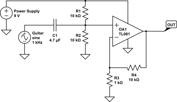
schematic

simulate this circuit – Schematic created using CircuitLab

In particular, I am wondering if it is necessary for me to bias the non-inverting input at 4.5V, and if this circuit would give me the desired gain of +10 if I build it correctly. This is not the specific Op amp I'll be using, I'm not sure which I'll be using yet, I haven't gotten that far.

\$\endgroup\$
3
  • 4
    \$\begingroup\$ Where does the bottom end of R3 go? You're showing it as unconnected and that's rather important. \$\endgroup\$
    – Finbarr
    Commented May 7, 2019 at 5:26
  • 3
    \$\begingroup\$ put a large cap in series with R3, to ground. \$\endgroup\$ Commented May 7, 2019 at 5:57
  • 1
    \$\begingroup\$ Note: guitar pickups are very high impedance. They do still work with a 5kΩ load, but it will completely ruin the response with the 1st-order low pass formed by the coil inductance and input resistors. I would recommend at least 200kΩ, if not 1MΩ. \$\endgroup\$ Commented May 7, 2019 at 15:06

2 Answers 2

21
\$\begingroup\$

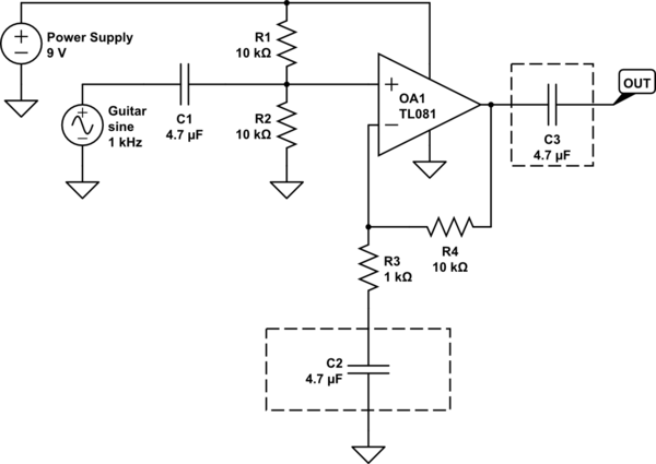
Your schematic should be as following:

schematic

simulate this circuit – Schematic created using CircuitLab

Since you're using a single-supply non-inverting amplifier, the non-inv input of the opamp should be biased to a non-zero voltage –ideally to Vcc/2 as in your schematic so that the amplified signal can swing equally.

Now let's take a look at the capacitors in dashed rectangles:

  • If you don't put C2, the DC bias will be multiplied by 11 as well. Thus the output will saturate and you'll never get the amplified signal from output. Since C2 will be open in DC, the net gain in DC will be unity. Thus the DC bias will be multiplied by 1. So the amplified signal will have an offset of Vcc/2 instead of 11 x Vcc/2.

  • C3 is just a DC-blocking capacitor. It removes the DC offset so you can get only the amplified AC signal.

\$\endgroup\$
3
  • \$\begingroup\$ Okay, that all makes sense, thank you very much! Now as a followup: will C2 and R3 + R4 create a low pass filter on the output of the op amp? \$\endgroup\$ Commented May 7, 2019 at 17:13
  • 1
    \$\begingroup\$ @alexamvdor Not one that will affect the output signal, no. It acts as a low pass filter for setting the bias voltage on the inverting input. \$\endgroup\$
    – Finbarr
    Commented May 7, 2019 at 17:33
  • 2
    \$\begingroup\$ @alexamvdor C2+R3 form a high pass filter and its cutoff frequency determines the low-end (i.e. -3dB point) of the amplifier's bandwidth. With the values above, this frequency is ~34Hz which means that the amplifier will never amplify the frequencies below 34Hz. This makes sense because in a standard-tuned six-string guitar the lowest frequency is 82Hz (low E). Even if you play a seven-string guitar (like me, hehe) the lowest frequency is 61Hz (low B) which is still in the bandwidth of the amplifier. \$\endgroup\$ Commented May 7, 2019 at 19:06
0
\$\begingroup\$

Because you have a single supply op-amp configuration, you would also need to bias the inverting input of your op-amp to +4.5V (Where did you connect R3?)

The gain will be (R3+R4)/R3 which is +11 for the resistor values shown here.

And you might also want to use a "bulk capacitor". (This is a short-time energy provider for your op-amp.)

\$\endgroup\$
0

Your Answer

By clicking “Post Your Answer”, you agree to our terms of service and acknowledge you have read our privacy policy.

Not the answer you're looking for? Browse other questions tagged or ask your own question.