For example, if one has a sensor which can be modeled as voltage
source call it Vs. Imagine it is outputting mV level voltage signals
and it has 1k output resistance. And if we want to amplify it we would
use an amplifier with a very big input impedance like 10Meg so that
most of the Vs reach the amplifier input.
You might do that if you are only interested in getting the most accurate measurement of open-circuit sensor voltage, but not if you want the best signal to noise ratio.
Suppose your amplifier has an equivalent input noise voltage of 1mV, and the signal is also 1mV. With a signal to noise ratio of 1:1 you will have a hard time separating them. But what if you use a transformer to match the source to the load? You want an impedance step-up ratio of 10M / 1k = 10000. The turns ratio required is the square root of the impedance ratio, ie. 100. Since the voltage step-up ratio is the same as the turns ratio, your signal voltage is now 100 times larger! Even after taking into account the 50% drop due to impedance matching, you still have 50 times more voltage than before (50mV vs 1mV). So by matching the impedances you have turned an abysmal 1:1 S/N ratio into a healthy 50:1 ratio (a 34dB improvement).
But what if you don't want to use a transformer? For a given temperature the thermal noise power in a resistor is constant, but the voltage is proportional to the square root of its resistance. So instead of increasing the impedance to match the amplifier, you could simply use an amplifier with lower input impedance - which (if properly designed) should have a proportionally lower input noise voltage.
The more signal power you can get into the amplifier's input, the more it has to play with for overcoming internal noise. Matching impedances produces maximum power transfer because although voltage reduces (compared to the open-circuit voltage), current increases. Though you lose 50% of the power in the source, you still get more out than with mismatched impedances.
Depending on how an amplifier is designed and the components it uses, the best S/N ratio may not occur when the impedances are precisely matched. As a general rule it will not be far off, but when comparing specific devices you need to examine the specs (or measure them). And there may be other criteria which are more important, such as sensor loading, linearity and dynamic range. Therefore we cannot say that matching impedances will produce the best results in all cases. Here are a couple of examples where matching impedance is not a good idea:-
Audio power amplifier: You want high efficiency to reduce power consumption and cooling requirements. Therefore the amplifier should have much lower impedance than the speakers, so that most of the power is delivered to the load. The low output impedance also helps to damp mechanical resonances in the speakers, producing more accurate sound.
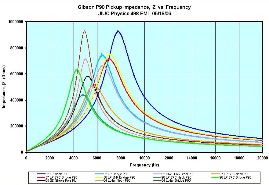
Guitar amplifier. The inductive pickup in the guitar has a complex impedance that rises as it approaches its resonant frequency, but so does the output voltage. To get flattest frequency response the amplifier should have a fairly high input impedance (typically around 100kΩ) but an even higher impedance is often desirable to increase the peaking effect at higher frequencies. The guitar may also have tone controls that modify the response. Matching its impedance at all frequencies would dramatically change the way the instrument sounded.


