22
\$\begingroup\$

I have some experience working with stm32 but I only ever used them on dev boards.

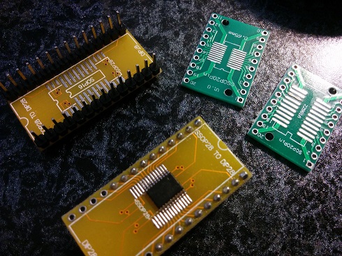
I recently tried to solder stm32 and stm8 on a simple break-out board and program them with my st-linkv2 clone. soldered stm32 on break-out board

On first power up, the mcu makes some little noises like burning after a few seconds, and 2 minutes later its drawing 100mA and smoking.

I think there is some important details that I'm missing. What could go wrong in a simple setup like this? (only vdd,vss, decoupling cap and st-link)

I tried over 20 times with both stm8 and stm32.

I got the decoupling cap as close as possible and supplied them with 3.3v.

A few times I was able to program and verify the flash but it showed some weird behavior * and again went up in smokes a few minutes later.

I tried drag soldering, regular soldering with smd tip and temperature as low as 260C and cooldown time after each pad. I also tried hot air gun on 270C and I'm close to sure the problem is not soldering.

I also tried with NRST pull-up and BOOT0 pull-down.

*weird behavior: "random" like timing on a simple led blinker or a pwm signal that only goes down to around 2.8v instead of 0v. overall its 'kinda' working but only for 1min.

** the problem is not st-link. its flashing the dev-board just fine

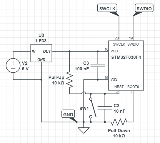
EDIT 1: Here's the schematic (for stm32)(Connections to ST-Link marked with labels):

enter image description here

enter image description here

there is nothing beneath. just another (unpopulated) footprint connected to pins.

EDIT 2: continuity test: no shorts, all pins contacts are OK

EDIT 3: connected VDDA and VDD and added another 4.7uF on VDD. still fried up. VDD measured directly on device: 3.36v

EDIT 4: current draw behavior: in all cases when the chip is fried, it draws around 20-40mA and sometimes suddenly goes up to 100-240mA for some seconds and then zeroes out(less than 10mA). and stays at zero for some time before start again.

UPDATE: i soldered another STM8S003F3P6,1uF on VCAP and 2x100nF and 10uF on VDD. and used a battery as source and made a little capacitance multiplier and emitter follower to make the 3.3v with lots of ceramic and low-ESR caps, and a current limit set on 15mA. the voltage had less than 30mV noise over 50MHz. then i connected the MCU (freshly soldered). current draw was less than 4mA and voltage was stable. i left it be. after a minute or two, it suddenly started to go over 15mA limit and trig the PDR. and now it starts to do that immediately (even with the NRST asserted). seems this one is gone too...

\$\endgroup\$
19
  • 6
    \$\begingroup\$ If you measure continuity/resistance between the pins a the bare breakout PCB, there are no hidden connections? (Measure pin 1 against 2...20, pin 2 against 3..20, etc) \$\endgroup\$
    – Huisman
    Commented Jun 20, 2019 at 11:48
  • 13
    \$\begingroup\$ My best guess is that you apply the supply voltage to the wrong place on your microcontroller. \$\endgroup\$ Commented Jun 20, 2019 at 12:17
  • 4
    \$\begingroup\$ Show us photos of your wiring setup. \$\endgroup\$
    – DKNguyen
    Commented Jun 20, 2019 at 17:35
  • 11
    \$\begingroup\$ With the absurd number of chips you've blown, there's something fundamentally wrong here. Try a completely different power source, like borrowing the 3v3 from the dev board. \$\endgroup\$ Commented Jun 21, 2019 at 14:02
  • 3
    \$\begingroup\$ How are you wiring everything up to these breakout boards? Posting a photo would be helpful. If it's a breadboard, is it damaged or faulty? To confirm that you don't have a defective or counterfeit batch of chips, you could replace the chip on your dev board with one of these and see if works there. \$\endgroup\$
    – echo
    Commented Jun 22, 2019 at 1:39

10 Answers 10

33
\$\begingroup\$

VDDA is not connected.

Application note AN4325 Getting started with STM32F030xx and STM32F070xx series hardware development says,

The VDDA supply can be equal to or higher than VDD. This allows VDD to stay low while still providing the full performance for the analog blocks.

When a single supply is used, VDDA must be externally connected to VDD.

So, connect pin 5 to pin 16 before trying again.

\$\endgroup\$
4
  • 1
    \$\begingroup\$ Noticed this in that application note - "The VDDA voltage level must always be greater than or equal to the VDD voltage level and must be provided first." \$\endgroup\$
    – HandyHowie
    Commented Jun 20, 2019 at 14:03
  • 5
    \$\begingroup\$ Simply connecting them works just fine. \$\endgroup\$ Commented Jun 20, 2019 at 14:12
  • 2
    \$\begingroup\$ @berendi i wasn't aware of this necessity. Thanks a lot. but i tied VDDA and VDD together and same thing happened. does VDDA actually needs to arrive "Before" VDD? the document says they can be tied together \$\endgroup\$
    – NXP
    Commented Jun 20, 2019 at 17:22
  • 1
    \$\begingroup\$ @Niko. I've seen it working with both power pins simply connected to each other. Pay attention to the capacitance requirements pointed out in other answers. \$\endgroup\$ Commented Jun 21, 2019 at 13:47
17
\$\begingroup\$

Have you looked at your power supply waveform with an oscilloscope?

The LF33 linear low-dropout voltage regulator you seem to be using requires a minimum of 2µF of added output capacitance for stability, your schematic only shows 100nF. Also, I don't see any input capacitance before the regulator.

If the regulator is oscillating, it could be intermittently applying the full 5V to your MCU power pins. That would exceed the maximum rating of 4V for the STM32.

\$\endgroup\$
10
\$\begingroup\$

IF you are not aware of CMOS "buried SCR latch effect" with supply shoot-thru heat-damage effects from inputs rising greater than supplying voltage by 0.3V, you will never forget now.

This is the same as applying analog signals before VddA is connected.

The application note p11 clearly states what must be done , but not the reason.

"• The POR monitors only the VDD supply voltage. During the startup phase, VDDA must arrive first and be greater than or equal to VDD.
• The PDR monitors both the VDD and VDDA supply voltages.
• However, the VDDA power supply supervisor can be disabled (by programming a dedicated option bit VDDA_MONITOR) to reduce the power consumption if the application design ensures that VDDA is higher than or equal to VDD"

\$\endgroup\$
4
  • \$\begingroup\$ i wasn't, thanks!. but what signals are coming before VDDA? in my power sequence i'm connecting VDD and VDDA (tied together) to 3.3, then connecting ST-Link. the application note says you can tie VDD & VDDA together. \$\endgroup\$
    – NXP
    Commented Jun 20, 2019 at 16:59
  • \$\begingroup\$ OK then ESD is another cause of this \$\endgroup\$
    – D.A.S.
    Commented Jun 20, 2019 at 17:21
  • \$\begingroup\$ see Edit 4. is this kind of current draw behavior due to latched-up damaged chip? \$\endgroup\$
    – NXP
    Commented Jun 20, 2019 at 17:31
  • \$\begingroup\$ Depends how hot it gets > 200'C for > 10s ?? but 1W I doubt.. Cause unknown \$\endgroup\$
    – D.A.S.
    Commented Jun 20, 2019 at 17:32
9
\$\begingroup\$

In my professional experience I have found the STM32 to extremely sensitive transient voltages on the power rails and GPIO. Make sure that your power supplies aren't over-shooting on startup. On thing you can do to mitigate this is to add between 10uF and 100uF on the output of your voltages regulator. Good luck and let us know how it goes.

\$\endgroup\$
7
\$\begingroup\$

Let's take a look into LF33 datasheet: https://www.st.com/resource/en/datasheet/cd00000546.pdf

Output bypass capacitance:
ESR = 0.1 to 10 Ω
Io = 0 to 500 mA
Minimum: 2μF, Typical: 10μF

Capacitance of 100nF, far away from LDO won't do the job. Try to check power line with oscilloscope. And do not fry next MCU without adding 10-47uF LOW ESR electrolytic capacitor near LF33 pins.

\$\endgroup\$
6
\$\begingroup\$

Where have you got the uC? Are they genuine?

I have worked with lots o f stmf1 and had no problems with esd nor higher temp soldering

Have you tried not flashing device? Just leave it on for some time.

Where are you getting power to 5v? Maybe it is some leakage from that. Try to power it from USB from same PC you are using the flasher. Try getting a ftdi converter for serial debugging and power it directly with the 3v3 output

From what I got, you simple test is blinking led. Right? What current are you using? Pin is attached on high or lower side? Try using a npn or similar fet on lower side to toggle this led. Maybe current is damaging it. Although I have seen it burn IO, not device like this.

Your school does not show vdda, not sure if it power anything other than adc, but it should not burn device too.

My best guess is the reference from different devices like power supply and usb

\$\endgroup\$
1
  • \$\begingroup\$ uCs were genuine. i tried not flashing the device (last post edit) led's were connected with 1K lowside \$\endgroup\$
    – NXP
    Commented Jun 21, 2019 at 13:52
5
\$\begingroup\$

Check the data sheet for the maximum current the F030 will draw and set the current limit on your bench supply to deliver a little less than that amount to protect the micro. I've not checked the data sheet for your LDO (LF33) but for stability you'll need a bulk capacitor on the supply side an a smaller value capacitor on the micro side. The latter is not to be confused with the decoupling cap for VDDD and VDDA on the micro. Finally someone else has already mentioned supplying the board schematic. Many of these 3rd party boards assume power and ground on the corner pins. That's not the case here. You will also benefit by using the free STM32CubeMx to help set your pins and generate the configuration code.

\$\endgroup\$
5
\$\begingroup\$

Stability of the regulator is the trick here. Light loads are harder to keep stable, without added capacitance.

I had a similar thing happen once with an LM317. The voltage in that circuit went towards 12v. Series control can go awry.

I worked with NXP Arm7 processors that had a power up latchup problem, on the I/o pins. I suspect your issue is the stability one though, not the latchup.

\$\endgroup\$
5
\$\begingroup\$

I finally found what was causing all these. Seems i had some problems in my grounding circuitry and some high voltage AC was appearing on the device during soldering and powerup and there wasn't a common ground present. Although the path was pretty high in impedance but apparently it caused a lot of harm... I've an STM8 blinking an LED for more than 5 minutes now!!! (What an achievement :) ) but i also didn't use soldering flux on this board, as i suspected the flux residues were making some problems too...

Update: the problem is fixed fore quite some time now and i can tell the main cause was flux residue. using good quality flux and properly cleaning the board before first powerup solves the problem entirely. i use liquid cleaners and hot air gun with minimum temp(150 'C) and maximum air pressure through narrow tip to "hot air" the liquid away from the chip and between pins, after it dissolves the flux residue. though using liquid on "baked" chips isn't the best idea, seems to solve the problem for now. if your on the same situation, I hope this thread helps you enough... thanks from everyone. I appreciate the time you put in :)

\$\endgroup\$
3
\$\begingroup\$

Mikołaj Tutak hit this on the head. Just a couple of notes.

The required ESR will be met by just about any cap. Throw a couple of cheap 10uF or 4.7uF electrolytics in parallel on the output and you'll be fine. The datasheet only calls for 2.2uF, but extra will not hurt.

I've used this exact MCU(and the K6 and CC for that matter) in at least 4 different designs. Never fried one. I used cheap MLCC caps for bypass, but on my input I had 10uf to 22uF solid AL caps;Except in one case, I had 10uF tantalum instead of AL. All of these designs were single layer on top of a ground plane. No regulator onboard.

In all of my testing my power supply was identical, 13.8V(From a radio PS) -> a 12V to 5V switcher(guts of a cheap USB power dongle, from a dollar store no less) -> 3.3V PS using a LM1084. About 120uF total on the output. Cheap 47uF x 2 and 10uF x 2.

\$\endgroup\$

Your Answer

By clicking “Post Your Answer”, you agree to our terms of service and acknowledge you have read our privacy policy.

Not the answer you're looking for? Browse other questions tagged or ask your own question.