1
\$\begingroup\$

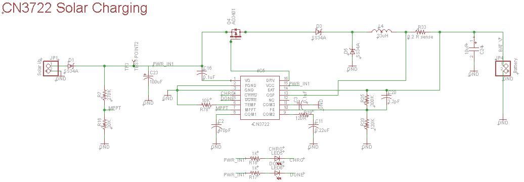
I'm using CN3722 for 2 cell battery charging. I have two way supply, it gets power from Solar as well as DC 12V whichever is available. The MPPT is set at 11V. Solar panel maximum goes to 21V.

I have two circuits. When I apply 12V the 'CHRG LED' blinks(Battery - NC) in both of the circuits, When increasing voltage to (13V-15V) the CHRG LED stops blinking(should blink) in one of the circuits. The charge current is set to 1A.

Both circuits have similar diagram and components but show different behavior. When I increase the voltage above 13V the battery is not charging in the faulty circuit whereas in the other circuit all conditions are working fine.

But when I measure the voltage of GATE DRV pin of IC, it started drawing the charge current. What might be the reason? enter image description here
\$\endgroup\$
1
  • \$\begingroup\$ so, if they have similar designs, they are not the same. Find the difference, figure out what it means. Since we don't know the difference, we can't help you. \$\endgroup\$ Commented Jun 22, 2019 at 15:17

1 Answer 1

2
\$\begingroup\$

I found the issue and resolved it. The GATE was directly connected to the DRV pin(as mentioned in datasheet) which was creating low resistance path. But when connecting the multimeter to measure the DRV pin voltage, means some extra resistance is added to that line and it was working. So I added a 22 ohm resistor between the GATE and DRV pin which worked well for me.

\$\endgroup\$

Your Answer

By clicking “Post Your Answer”, you agree to our terms of service and acknowledge you have read our privacy policy.

Not the answer you're looking for? Browse other questions tagged or ask your own question.