31
\$\begingroup\$

enter image description here

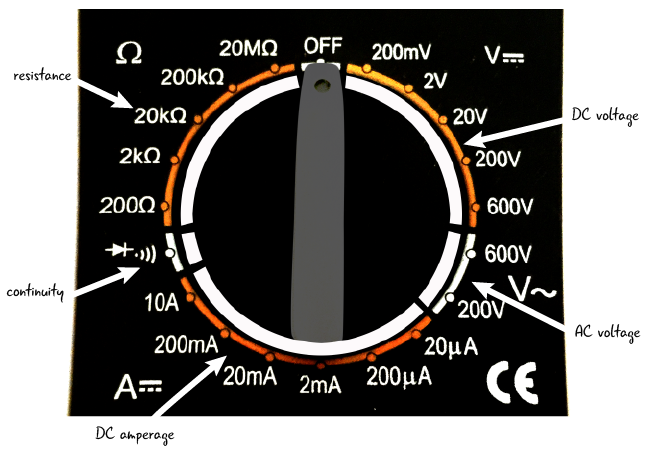
Everyone who has ever handled a multimeter is familiar with these dials. The position of the dial indicates the maximum range of the quantity that can be measured.

But why are we required to adjust the maximum range ourselves? What happens internally in the multimeter when the dial is adjusted, say, from 20V to 200V? If we have the dial on 20V, and the voltage measured is 50V, why can't the meter provide a measurement? I don't have much knowledge on the internal workings of a multimeter, but I understand that voltage is measured by letting an infinitesimal amount of current through the meter and measuring the magnetic field (something along these lines). But why can't the meters adjust their range themselves?

EDIT: I know there are autoranging meters, but I'm interested in knowing why others have to be adjusted manually.

\$\endgroup\$
3
  • 5
    \$\begingroup\$ Cost........... \$\endgroup\$
    – Chu
    Commented Jul 5, 2019 at 14:36
  • 8
    \$\begingroup\$ Sometimes the auto-range behavior is a seriously-irritating behavior. A fixed range can be your (circuit-understanding) friend. \$\endgroup\$ Commented Jul 5, 2019 at 16:01
  • 3
    \$\begingroup\$ @analogsystemsrf Though every autoranging meter I've seen does have a manual range option as well. It's a little less straightforward than just turning the dial, but I think the mild inconvenience when you need to set it to a fixed range is worth it for the convenience of autoranging. \$\endgroup\$
    – Hearth
    Commented Jul 6, 2019 at 17:02

5 Answers 5

30
\$\begingroup\$

enter image description here

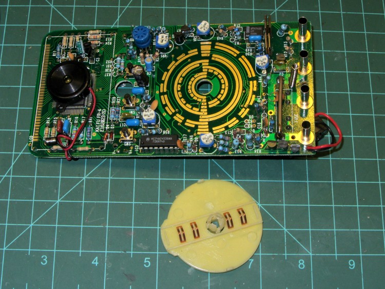
This image (source) ought to tell you all you need to know about how it works. There are wiper contacts on the dial, shown at the bottom, that mate with pads on the meter's PCB.

These pads are connected to different taps of a voltage divider to divide the voltage, or to pass current through a current shunt.

Internally, the meter can only measure voltages from, say, -0.2V to +0.2V. The range switch changes the voltage divider to prescale the input voltage to be within that range, and on most meters will also send a signal to the LCD to tell it where to put the decimal point.

As for why you have to do it yourself instead of the meter doing it for you: Nothing more and nothing less than price. A meter that auto-ranges is more expensive than one that doesn't due to the need for additional hardware to detect when it's over-range and perform the switching.

\$\endgroup\$
9
  • 4
    \$\begingroup\$ "Internally, the meter can only measure voltages from, say, -1V to +1V." It is more than likely the lowest DC V range. ±199.9 mV on the basic digital meters. "... so the multimeter chip can digitally multiply that voltage back up ..." It's easier than that; one pole of the switch selects the relevant decimal point. No multiplication required. \$\endgroup\$
    – Transistor
    Commented Jul 5, 2019 at 13:21
  • 1
    \$\begingroup\$ @Transistor I used that value just as an example, as I don't know what a typical range would be. Good point about it being the lowest range, though. \$\endgroup\$
    – Hearth
    Commented Jul 5, 2019 at 13:25
  • 5
    \$\begingroup\$ I only know that much because I built a multimeter using one about 40 years ago. They seem to be pretty much the same devices in the €5 meters available in the supermarket these days. Mine cost me a lot of pocket money at the time. \$\endgroup\$
    – Transistor
    Commented Jul 5, 2019 at 14:45
  • \$\begingroup\$ @Transistor Ah, the march of progress! \$\endgroup\$
    – Hearth
    Commented Jul 5, 2019 at 14:46
  • 2
    \$\begingroup\$ "A meter that auto-ranges is more expensive than one that doesn't due to the need for additional hardware to detect when it's over-range and perform the switching." I wonder whether that's still really true.That big, mulicontact rotary switch costs a fair amount of money. A coarse A2D plus a comparator might well be cheaper. It wouldn't surprised if the current design continues more through inertia than real cost savings. \$\endgroup\$ Commented Jul 6, 2019 at 15:32
19
\$\begingroup\$

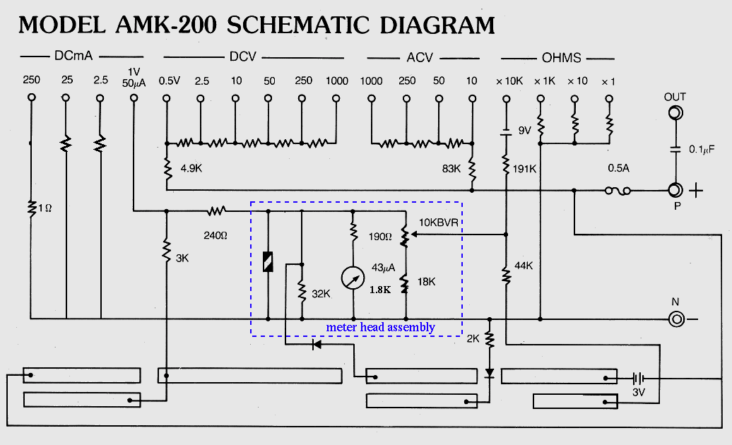
An old analog meter may be easier to understand (source http://fourier.eng.hmc.edu/e84/labs/lab1/node1.html):

enter image description here

Since the gauge deflection depends on the current passing it, and the deflection/current ratio does not change, different contact positions will form different voltage or current dividers to adapt the scale. Note: the coil resistance is also fixed.

It's not that different with digital meters, except that instead of a coil that needs a certain current it has a Analog to Digital Converter (ADC) which needs a certain voltage for full scale indication.

\$\endgroup\$
4
\$\begingroup\$

If it is a digital multimeter, it works differently than an analogue one.

The schematics for an analogue one is shown in Vangelo's answer.

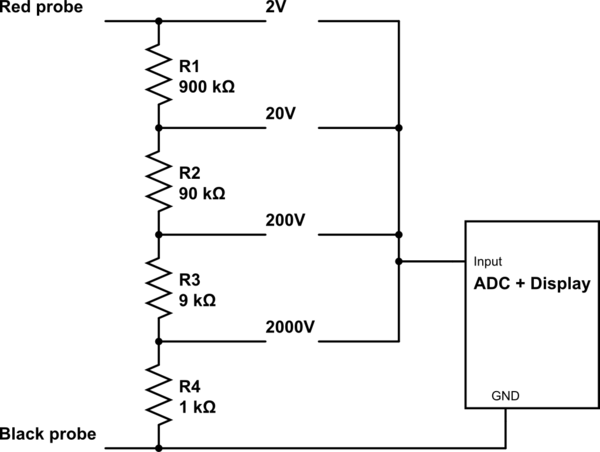
The schematics for a digital one looks like this:

schematic

simulate this circuit – Schematic created using CircuitLab

For the voltage measurements, the dial will select the ratio of the voltage divider (as shown in the schematics above) and it will change the position of the decimal dot on the display.

\$\endgroup\$
3
\$\begingroup\$

A voltmeter is not measuring any currents. There is an ADC (analog to digital converter, that is the real measuring device) inside, which compares the input voltage with a reference voltage and gives the factor of the input to the reference as a digital output.

Let's say the reference voltage is 2V. Then the maximum input voltage is also 2V, because this would be 100%. If you turn the dial to 20V input range you are switching in a voltage divider to the input, so that you reduce the input voltage by the factor of 10. This results in only 2V at the ADC with 20V input voltage. The microcontroller knows that and shows you the real value on the display.

Autoranging meters can choose the different voltage dividers by switching relays. This requires additional parts and therefore some meters just have the user set it manually and by that reducing cost.

\$\endgroup\$
1
  • 6
    \$\begingroup\$ Well, old passive analog meters "measure current" in the sense that they need current passing through the meter movement to swing the needle. A meter movement that required 50\$\mu \mathrm{A}\$ was the common "high class" standard; that translates to a 20000\$\Omega / \mathrm{V}\$ meter. \$\endgroup\$
    – TimWescott
    Commented Jul 5, 2019 at 16:54
1
\$\begingroup\$

In simplest form the dial switches suitable resistors between probes and meter coil so that multiple ranges of voltages and currents cam be measured with a single meter.

If you try to measure 40V at 20V range then the meter would have to go to 200% reading because there is two times the current flowing it needs to display 100% reading. The coil cannot move the meter physically and the coil might burn because of excess current flowing unless there are protection components to limit it.

The meter does not know how much voltage you are about to measure and has no active components to detect or switch the range automatically.

\$\endgroup\$
1
  • 4
    \$\begingroup\$ You're talking about a coil; it might be worth mentioning digital multimeters with ADCs as well. \$\endgroup\$
    – Hearth
    Commented Jul 5, 2019 at 16:06

Your Answer

By clicking “Post Your Answer”, you agree to our terms of service and acknowledge you have read our privacy policy.

Not the answer you're looking for? Browse other questions tagged or ask your own question.