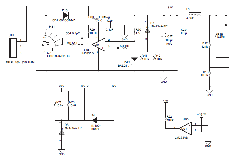
Usually an unused comparator (like U6B) is connected thusly to keep it's output stable. If left unconnected or tied to the same rail internal noise could make it switch states randomly and perhaps quickly. However it really shouldn't be necessary as the comparator is open drain. Just leaving R22 open should give the same effect. Biasing the inputs like that doesn't hurt though.
About the only thing I can see with R43 and C34 is that because R43 is there C43 allows U6 to turn the fet off faster than if it wasn't there. The fet has 1000-1500 pF gate capacitance and when U6.1 goes low C34 shorts out R43 long enough to discharge the fets gate capacitance. It doesn't help on speed up, however because R29 and the gate capacitance set the risetime. However it's not clear why R43 is there. Some comparators and opamps with push-pull outputs can be unstable with large capacitive loads so a resistor between the output and the load stabilizes it, but I don't think its required with an open drain configuration.
As for thresholds your analysis is wrong about the non inverting input. D7 is a 6.8 V zener diode and as soon as the 39V rail gets to 6.8 + about 0.7 (~7.5V) the comparator output will go high. R41 and R42 are in parallel with each other and simply bias the zener. Why they use such a low value is unclear. Furthermore there is a nuance in the design involving R30 and R31. R30 implements some positive feed back. When the comparator is high the feedback voltage raises the non inverting a bit, and when the output is low lowers it a bit changing (slightly) the thresholds in such a manner that once the comparator changes state it tends to stay changed. This technique causes a property called hysteresis in the Vout-Vin curve of the comparator circuit. What voltage it switches at is a function of the present output state. The amount that the threshold changes by is close to R31/R30 * 16V

