6
\$\begingroup\$

I understand DC power more than AC power. I know that given multiple DC power generators, easiest way to sum them is by connecting them in series. In paralel you'd need every generator circuit to protect itself from reverse current coming from other generators.

But I'm currently learning about solar PV systems and noticed that 'net metering' is just us putting our inverter paralel to the grid.

Thing is I am really not knowledgeable enough about AC to make this oversimplification - is it really that easy?

\$\endgroup\$
3
  • 3
    \$\begingroup\$ Protecting a DC generator against reverse current may be done using a diode only. Implementing current balancing between paralleled DC generators is not that easy. \$\endgroup\$
    – Uwe
    Commented Aug 26, 2019 at 15:12
  • 3
    \$\begingroup\$ "is it really that easy?" Nope! \$\endgroup\$
    – Alexander
    Commented Aug 27, 2019 at 17:14
  • 2
    \$\begingroup\$ @Alexander That one was brilliant! I will share it along my HVDC colleges :-) \$\endgroup\$
    – winny
    Commented Aug 27, 2019 at 22:06

4 Answers 4

10
\$\begingroup\$

Question isn't clear. What do you mean with "sum"?

Differences are pretty complicate but, I attempt the silly thing to describe it in 2 sentences.

If you place DC sources in series, you get the voltage equal to the sum of all the sources' voltages. If you place them in parallel - given a diode between each positive lead, to avoid short circuits (author's note: thanks to the user in the comments) - you get the voltage equal to the higher source voltage. About current: when they are in series they all supply an equal amount of current as far as they all can supply the requested amount; when they are in parallel instead, the one with higher voltage supplies the load alone until it lower the voltage (because can't sustain that power request) or fail.

AC is similar, actually more complicated. To start you MUST put the 2 sources in sync, otherwise any bad thing can happen. Usually what you do is checking the zero crossing point and use it to sync the two AC sources...

You probably see the AC being easier because solar inverters usually have connections to sync when connected in parallel.

That said, I invite you to start reading the basics and use your application as a learning tool, before attempting any experiment. Because it can be expensive and dangerous to hands on without the basic theory.

\$\endgroup\$
7
  • \$\begingroup\$ By summing I meant 'add', as in share the burden of a load together. \$\endgroup\$
    – Evan
    Commented Aug 26, 2019 at 14:24
  • 3
    \$\begingroup\$ When putting multiple constant voltage sources in parallel, you don't get "the voltage equal to the higher source voltage". You just get a short circuit. Try putting a 9V battery in parallel with a 1.5V LR20 one (or maybe don't: I can't even say what will happen, but you certainly won't get 9V). \$\endgroup\$
    – dim
    Commented Aug 26, 2019 at 15:09
  • \$\begingroup\$ @Evan please, have a look at voltage and current, and the relationship between them. They 'share the burden' both in parallel and in series. But they share it in a different way. You can't put an unlimited number of sources in series, because soon or later your voltage will be too high. But you can put an unlimited number of sources in parallel (using a diode in between) and they will all (some sort of) share the load... \$\endgroup\$
    – Anichang
    Commented Aug 26, 2019 at 15:33
  • 1
    \$\begingroup\$ @Anichang, if you try to do diode sharing, and the higher-voltage source can't handle the whole current load, you're likely to get an output equal to the lower-voltage source's output rather than the higher-voltage source's output. \$\endgroup\$
    – The Photon
    Commented Aug 26, 2019 at 17:13
  • \$\begingroup\$ Depending on so many details of how the sources are implemented that it's silly to try to write a general rule in one sentence. \$\endgroup\$
    – The Photon
    Commented Aug 26, 2019 at 17:13
36
\$\begingroup\$

Because UL 1741 does all the heavy lifting for you.

That's what makes it "so easy". UL 1741 is a complicated spec for "grid-tie solar inverters".

Aside from doing their usual inverter thing (itself no small matter), a 1741 inverter also senses the presence of the grid, and obviously syncs its output to the grid.

A UL 1741 inverter is intentionally designed to be unable to function without the grid giving it a heartbeat. It cannot standalone. It cannot blackstart. Why? A basic rule of using the shared power grid is you're not allowed to backfeed onto a dead grid. If you have a generator in your house, you must have a transfer switch or generator interlock that guarantees utility and generator are on opposite sides of a double-throw switch, making sure they can never connect to each other.

The reason is if there's a power failure, your generating source would energize the lines to your house, which would energize the secondary of the poletop transformer at 240V, which would energize the primary at 2400V, ditto ditto the distribution transformer at 19200V -- and suddenly downed wires, that the power company had certified as de-energized, are lit up again. Some poor lineman who is out in the rain, cold and dark getting your power back on for you, who didn't attach ground-outs because it would slow things down, becomes a sad casualty.

Because the UL 1741 inverter is designed to backfeed onto the grid, it must monitor utility power for its presence, and "follow" it. Most power plants work this way, in fact; precious few can spin up alone or "blackstart" the grid, generally hydro.

There's another factor: Rapid Shutdown. This is a required feature of rooftop solar installations, i.e. Where firemen may have to work around the solar panels with fire-axes and water. This requires the solar panels either disconnect or segment themselves so within-panel-group voltage is <80V and across-aisle voltage is <30V. Firemen need to be able to push a button to make that happen. The easiest way to implement Rapid Shutdown is at the UL 1741 inverter; have the inverter command Rapid Shutdown whenever the grid is down (or to be more precise, command Rapid startup when the grid is up :). So the fire department need only do what it already does, pull the house's main breaker / meter. So this too must go into the inverter design.

This is a real eye-opener if you expected solar power during a blackout

For that, you need a more complex system like this. Bonus points if you add a DC panelboard and supply as many household loads as possible on DC (lighting, TV, router/modem etc.)
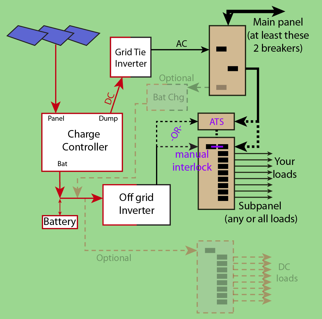
enter image description here

This is a simple system with one-way power flow in all cases (except battery obviously). They make much more complicated systems designed to bolt on to existing grid-tie systems where the battery-inverter is one module with one cable connection; this makes the "don't backfeed" interlocks a lot more complicated.

Mind you, it's absolutely possible to build a UL 1741 compliant grid-tied inverter that fails over into disconnecting itself from the grid, the grid from your panel, and your panel to itself and then blackstart into your own panel to light up local appliances. But at that point you're switching 3 sides of a triangle with some pretty critical interlocked switching. And the inverter has to operate in two wildly different operating regimes; may be simpler to have 2 inverters. So this is not the unit you'll get by default when the solar salesman comes knocking.

\$\endgroup\$
6
  • \$\begingroup\$ Whoa thank you for this! It's like you read my mind on what I'm trying to understand/learn about but fall short on finding better resources online. However my question was way simpler and the other has answered sufficiently so I had to accept that. \$\endgroup\$
    – Evan
    Commented Aug 27, 2019 at 2:48
  • \$\begingroup\$ One quibble: it is permissible for a UL 1741 inverter to provide a standby output, but that means the inverter must provide an internal transfer means to disconnect itself from the grid during grid failure (look at a Victron MultiPlus, Schneider Conext XW+, or Outback Radian GS for how this is done) \$\endgroup\$ Commented Aug 27, 2019 at 23:45
  • \$\begingroup\$ @ThreePhaseEel Good point. I excluded the possibility in my mind because the vast majority of installed base doesn't have that feature. \$\endgroup\$ Commented Aug 28, 2019 at 0:24
  • \$\begingroup\$ @Harper -- yeah, it's not a feature that plays well with the trend towards transformerless inverters. \$\endgroup\$ Commented Aug 28, 2019 at 0:39
  • \$\begingroup\$ In Europe, these are called Hybrid inverter because when there's no grid, they switch mode to work like a off-grid inverter. \$\endgroup\$
    – xryl669
    Commented Aug 28, 2019 at 12:30
14
\$\begingroup\$

It is really not that easy. It's easy for you because standards and regulations have been put in place that affect the power company and anyone selling you grid-tie inverters. The system is designed and regulated by law so that you can just buy a shiny box, pay someone to hook it up, and not worry.

The grid-tie inverter is pretty complicated. It has to sync to the grid "nicely", and it has to detect when the grid is down and shut off (so that when power goes out the electrical workers aren't killed trying to restore it).

Shoving power into the grid also tends to destabilize the grid, which is a growing problem for power companies in places where there's a lot of decentralized alternative energy sources. Grid managers (i.e., the power company) have to deal with this, and it's feeding all the way back to the grid-tie inverters in some jurisdictions (Google for "managed grid-tie inverter").

\$\endgroup\$
0
1
\$\begingroup\$

The idea in such inverter is to monitor the voltage across the output it's connected to. The expectation is that the grid will consume all the current it is generating. So, it only need to ensure it can inject current in the grid.

How is it doing that?

The algorithm is quite simple, it starts to output a voltage that's a few volt above the main line for a very small time and it monitors the current flow.

If the main line is powered off (because the utility guy is working on the line), the current will not increase and the voltage will not change, the inverter stops the injection (and retry later).

If the main line is active, then because you now have a higher voltage source from your inverter, the current will flow from your inverter to the nearest consumer.

If the nearest consumer is drawing too much current, the voltage will decrease and as soon as it reaches the main line voltage, the grid replace the current source.

Let's say you've switched off your power breaker and plugged a UPS or a diesel generator to expect your inverter to inject more current in your home that any of them alone.
That would not work because the inverter expects the load to be able to consume all the current it's producing, so it'll raise the voltage until the current matches what it's producing. That means that if you don't have a consumer on your installation that's exactly balanced with the production, the voltage will skyrocket, likely burning some electronic board on your UPS or generator.

Hopefully, inverters also monitor the voltage and stop injecting if the voltage goes crazy high.
If you use, for example, your water boiler as a load, then again that will not work as, as soon as the inverter is not producing enough current for the boiler, the voltage will decrease going out of spec. That will likely burn some fuse first as the current will skyrocket to match the expected power spike.

So said differently, offgrid inverter and ongrid inverter are very different because the former is monitoring the load and adjusting the production for the load while the latter is monitoring the line to inject all of the production (expecting the grid to absorb all the generated power)

Hope this help to understand in simple words.

\$\endgroup\$

Not the answer you're looking for? Browse other questions tagged or ask your own question.