1
\$\begingroup\$

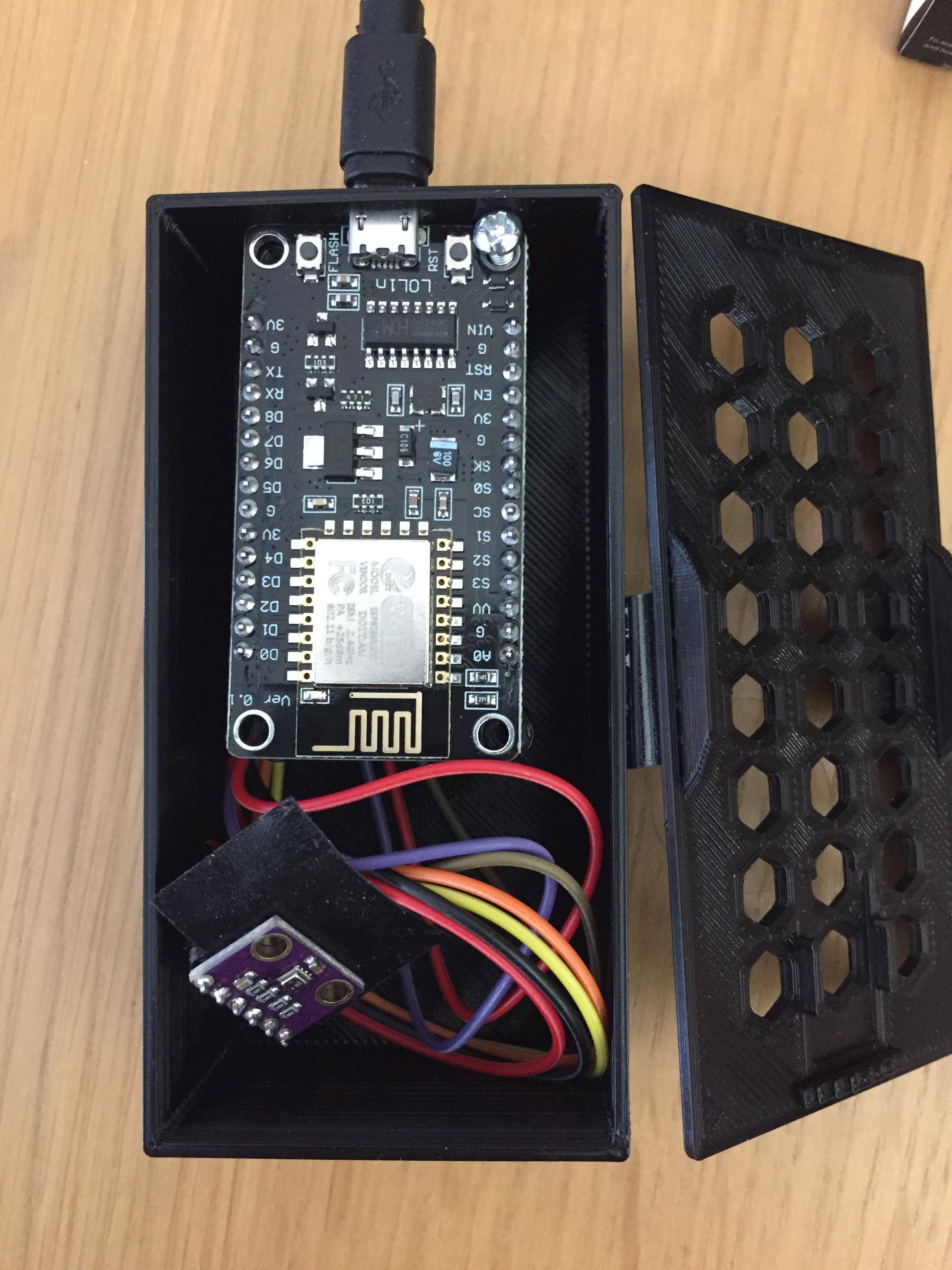
I have built a little thermostat based on BMP280 temperature sensor over I2C, ESP8266 Lolin v3 and STX882 433Mhz transmitter.

I have not added additional pull-up resistors or decoupling capacitors.

Everything works fine when the components are out of the enclosure (see picture), but when I put them inside the enclosure the BMP280 readings start to 'oscillate' as shown in this pictureSee the oscillation after 18:00. Ignore the spikes, that was me touching the sensor.

I am not an electrical engineer and the only thing I can think of is that there is some kind of interference between the transmitter and the BMP280 or I2C bus.

To give you and idea I am also attaching two pictures of the thermostat. Closed enclosure Open enclosure

Any suggestion?

\$\endgroup\$
14
  • \$\begingroup\$ I'd try to fix the position of the transmitter module and the BMP280, I would glue them to the bottom of the case. I would use a glue-gun as then it is easy to remove the glue and try a different position. Fold the wires (like a harmonica) and use a cable tie, elastic or a piece of wire to keep the wire folded. That will make the inside of the box look "more neat" but also could prevent circuits interfering with each other. \$\endgroup\$ Commented Sep 11, 2019 at 6:03
  • 3
    \$\begingroup\$ @Rojj - Hi, "I am not using pullups resistors or decoupling capacitors". I think you mean that you have not added additional pull-up resistors or decoupling capacitors. That photo of your BMP280 module appears identical to this one which clearly shows that it has (weak) 10k I2C pull-up resistors and a decoupling capacitor already fitted. I don't have time to write a troubleshooting answer now, but I suggest you edit the question to clarify the point above, as it could mislead readers that there are no I2C pull-ups. \$\endgroup\$
    – SamGibson
    Commented Sep 11, 2019 at 6:33
  • 1
    \$\begingroup\$ One obvious problem is the numerous antennas you have created. Keep the wires as short and straight as possible! Also, this is a hobbyist radio so you get what you pay for. Is it even legal to use in civilized countries with radio laws (CE and/or FCC)? \$\endgroup\$
    – Lundin
    Commented Sep 11, 2019 at 7:44
  • 1
    \$\begingroup\$ Temperature sensor is in box with ESP8266 consuming 150mA. 150mA maybe is not a lot, but can produce some heat power. Controler propably sleeps for 3 minutes, do measurment (heating box internal), transmit data and sleeps again. Try to put sensor out of box or in other box. \$\endgroup\$
    – ufok
    Commented Sep 11, 2019 at 8:17
  • 1
    \$\begingroup\$ First step is a sound circuit design, next is to transmit after taking a reading, not during. And then you worry about self heating... \$\endgroup\$ Commented Sep 11, 2019 at 11:47

3 Answers 3

1
\$\begingroup\$

Maybe a basic solution, but it was sufficient to move away the RF Transmitter. I have actually hidden it under the LoLin.

enter image description here

enter image description here

\$\endgroup\$
0
\$\begingroup\$

One thing you can do if there is still some noise: shorten the cables of the sensor or shield them. The longer the sensor cables, the more they'll function as "antennas"

\$\endgroup\$
-1
\$\begingroup\$

Try Faraday shielding the sensor. Ofcourse that would make the sensor system inaccurate but will help consolidate that it is infact caused by EMI. The faraday shield can be as simple as wrapping the sensor in some plastic wrap followed by covering it with some aluminium foil.

\$\endgroup\$
5
  • \$\begingroup\$ Your plan would not really accomplish shielding especially as the wires would run inside your unconnected and rapidly oxidized foil. Further, the sensor already has its own version of that as the package of the BME280 is metal with a tiny port hole. \$\endgroup\$ Commented Sep 11, 2019 at 11:48
  • 1
    \$\begingroup\$ By Faraday caging I did mean having the foil connected to ground, it is not a solution just a small experiment to confirm if it really is the interference from the 433MHz module so oxidization is of little concern. If the cause is really the 433MHz transmitter I'd suggest shutting down the module before reading data from the BMP280 sensor and later turning on the module to send it. \$\endgroup\$ Commented Sep 12, 2019 at 4:05
  • \$\begingroup\$ The problem with aluminum foil which you seem unaware of is that it all but immediately oxidized in air. Because aluminum oxide is non-conductive (unless pierced by voltage or mechanical abrasion), that means that it's very hard to actually connect it to ground - it is not used for this in practice. And besides, it's pointless because, as already mentioned, the sensor comes in its own well designed shielded housing. \$\endgroup\$ Commented Sep 12, 2019 at 4:38
  • \$\begingroup\$ I get your point. Thanks for pointing out the notorious behaviour of Aluminium, I wasn't aware of that. I thought PCB traces could act as antennae and couple RF noise which the shield doesn't take care of. Any thoughts on this? \$\endgroup\$ Commented Sep 17, 2019 at 4:28
  • 2
    \$\begingroup\$ Traces can couple noise, yes, but the shield can built right into the sensor is going to do a better job than any external shield. You can put ferrite beads on traces - but again, that is relatively beside the point, because with a very low duty cycle radio, the obvious solution is not to take a reading and operate the radio at the same time. \$\endgroup\$ Commented Sep 17, 2019 at 4:35

Your Answer

By clicking “Post Your Answer”, you agree to our terms of service and acknowledge you have read our privacy policy.

Not the answer you're looking for? Browse other questions tagged or ask your own question.