2
\$\begingroup\$

I want to build a DIY power bank that can be powered using most types of laptop chargers. I do not have any background except personal interest and lots of videos and documents read online. I need someone with more experience to please have a look at my circuit and let me know if it is going to work or if I'm building a time bomb :)

I will include all the component specs and links for convenience.

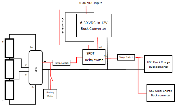
enter image description here

I will use a 3S10P battery pack built from reclaimed li-ion cells from dead laptop batteries.

I am hoping to have sort of a 'plug n play' functionality to avoid using switches (plug in charger to automatically start charging the powerbank, or plug in phone and immediately start charging it).

I am planning to use a relay switch for this to avoid a simltaneous charging/discharging scenario where a charger is connected when a phone is charging.

The relay is connected such that the Normally Closed (NC) contact is connected to the output (phone QC converters), while the Normally Open (NO) terminal is connected to the step down buck converter output (used for charging the powerbank). The control circuit is powered by the input of the buck converter. This way (at least the i think it will work), when a charger is connected, the output is disconnected so that I can't use the powerbank to charge my phone when it is charging.

Component links & specs:

What i need help/guidance with:

  1. I want to charge/discharge each cell at 1A max. Is there a chance that the the circuit may draw more than this? Don't want to be too harsh on the reclaimed cells.

  2. Temperature switches trigger at 45 celcius. Is that safe for li-ion?

  3. Is there need for a cooling fan for the buck converter used to charge the powerbank? Output will be 12.6V 10A and input will depend on charger used. Most laptop chargers i've seen output between 12-20V at 4-10Amps

  4. What changes/additions or general suggestions would you recommend?

\$\endgroup\$
1
  • 3
    \$\begingroup\$ A DIY powerbank using lithium cells that actually has a BMS and overall fairly sensible design, that's a rarity on here! \$\endgroup\$
    – Hearth
    Commented Oct 14, 2019 at 20:22

1 Answer 1

2
\$\begingroup\$

I want to charge/discharge each cell at 1A max. Is there a chance that the the circuit may draw more than this?

Yes, it could draw more than 1A. Your 'USB Quick Charge buck converters' are rated for up to 24W output, so if they were both used to capacity the input power would be more than 48W. 48W/11.1V = 4.3 Amps.

Temperature switches trigger at 45 celcius. Is that safe for li-ion?

Yes.

Is there need for a cooling fan for the buck converter used to charge the powerbank? Output will be 12.6V 10A

Assuming the specified 95% efficiency is correct, the converter wastes 5% of the input power. At 12.6V 10A out that would be (12.6*10)/0.95)*.05 = 6.6 Watts. At 10A you would need a cooling fan if there was insufficient natural convection. However since the battery charging current is limited to 1A the converter will never have to deliver more than 1A, so it probably won't get hot enough to need a cooling fan.

Overall your circuit looks like it will work, but is it safe? The only issue I can see (apart from making sure the charging voltage and current are set correctly) is that you have no over-discharge protection apart from the BMS. If the BMS low voltage cutoff is below 3.0V per cell then the battery could get discharged to the point where it should be recharged at a lower current.

\$\endgroup\$
3
  • \$\begingroup\$ Thank you for your answer. I think i was not very clear, but your calculations have helped me understand the answer still. I think... I wanted 1 Amp to be the max draw for a single cell in the battery pack. Please correct me if I'm wrong, but i think that if i have 10 cells in parallel, i should get 10A and 11.1 nominal voltage for 3 cells in series (i'm using 30 cells in total). So this should mean that if both converters are working at max, they pull 4.3 Amps, and each individual cell will see a max draw of 430 amps. Right? \$\endgroup\$ Commented Oct 14, 2019 at 22:09
  • \$\begingroup\$ Also, considering that I also want to charge each individual cell at 700mA, does that mean the charging current will still be limited to 1A? I'm hoping to have the output at 7A to charge the cells a little faster. \$\endgroup\$ Commented Oct 14, 2019 at 22:12
  • \$\begingroup\$ Lastly, which other over-discharge protection would you recommend I add apart from the BMS? \$\endgroup\$ Commented Oct 14, 2019 at 22:12

Your Answer

By clicking “Post Your Answer”, you agree to our terms of service and acknowledge you have read our privacy policy.

Not the answer you're looking for? Browse other questions tagged or ask your own question.