0
\$\begingroup\$

So, we did our lab activity and I don't quite understand the question

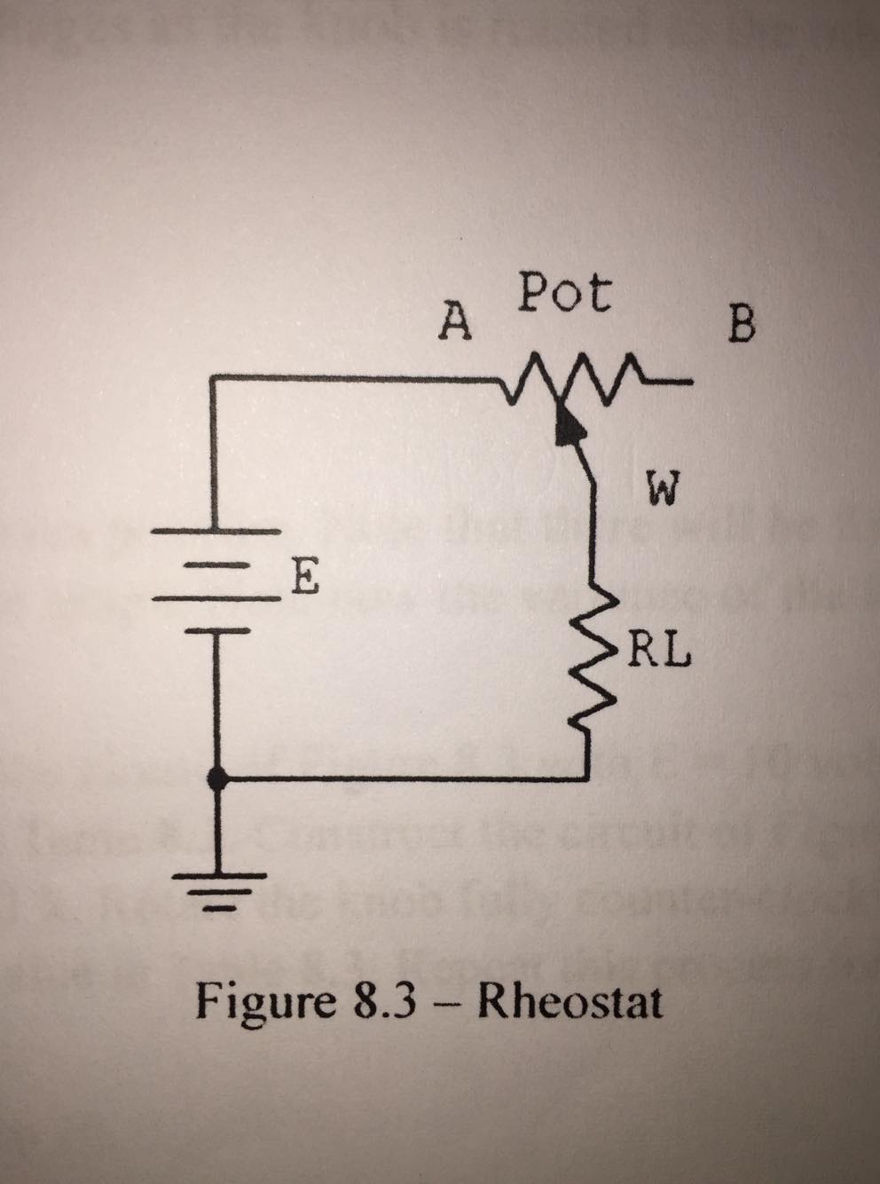
"How could the circuit be modified so that the maximum current could be set to a value higher than that achieved by the supply and load resistor alone?"

Here is the circuit diagram: enter image description here

The voltage supplied is 10V and the potentiometer value is rated 100K ohms. The RL value are 1k and 4.7k ohms.

Here is the data I measured:

enter image description here

My initial thought would be that the total resistance be lowered, since V/R = I.

\$\endgroup\$
2
  • \$\begingroup\$ I'm wondering whether they mean "how can you you draw more current from the battery than the case when you connect RL directly across the battery terminals?" If that's what they mean, then having the pot's A and B pins across the battery terminals, in parallel with RL, would results in (slightly) higher current. \$\endgroup\$
    – joribama
    Commented Nov 1, 2019 at 7:35
  • \$\begingroup\$ Thanks for the insight! \$\endgroup\$
    – MIGGYEE
    Commented Nov 1, 2019 at 7:38

1 Answer 1

0
\$\begingroup\$

This question is probably related to the maximum power transfer theorem that states that: " to obtain maximum external power from a source with a finite internal resistance, the resistance of the load must equal the resistance of the source as viewed from its output terminals".

In reality, all sources of electrical power have an output resistance (or impedance in a more general sense) to compensate the limited power available. So, in order to maximize power, the load resistance RL "must be" equal to the source resistance (not shown in your circuit).

If you want an deeper explanation on this I would recommend the book by Hayt.

I hope this helps.

\$\endgroup\$

Your Answer

By clicking “Post Your Answer”, you agree to our terms of service and acknowledge you have read our privacy policy.

Not the answer you're looking for? Browse other questions tagged or ask your own question.