1
\$\begingroup\$

Background:

I have a set of irrigation control valve solenoids (24V ac) that I control via a set of mechanical relays with the GPIO pins of a microcontroller (ESP32). The power supply does not have a large enough current to operate two valves at once, which is fine because the system also does not have enough water pressure to run two zones at once.

In theory, I should be able to limit the system to one valve at a time strictly in software, but I keep finding corner cases where I have not ensured that, and when I mess up the supply voltage to the IC drops below 3v and the system reboots, so debugging is a pain.

Question:

Is there a reasonably simple circuit I could construct that would prevent a second pin from going high if another one is already on?

Bonus points if there is an output that I can use to trigger an interrupt when this happens.

UPDATE:

Several people have asked about a software solution.

Yes, I did refactor my code so that pins were set in exactly one place. I missed one piece of code in the refactor. sigh I also had an interesting bug where an internal process still wrote to an external pin when writing to flash memory. The ESP32's GPIO matrix makes it pretty hard to ensure that a library never accidentally takes over a pin.

So while I agree that the software solution is ideal, my lived experence is that I would benefit from some hardware fault protection here.

\$\endgroup\$
5
  • 2
    \$\begingroup\$ Let me put this another way. Tell me if I'm totally off-base. You are having software problems and would like a hardware fix which over-rides the stupid software and prevents it from screwing things up... Is that about it? My tendency would be to blame the software for this problem -- or, at least, blame it for not sufficiently taking into account the physics going on with controlling external mechanical relays well enough to get the job done right. \$\endgroup\$
    – jonk
    Commented Dec 4, 2019 at 22:59
  • \$\begingroup\$ If you have control of the software and you are willing to change that software, you might simply use a combination of I/O ports as a binary number that indicates the zone you want activated (and maybe a binary "zero," if no zone.) If you feed that into a "decoder" then you will only get one output line enabled as a guarantee of the device. You can then use those outputs just like you do now with the GPIO pins. Just a thought to consider, if it helps "debug" the software and hardware combination you have going on right now. \$\endgroup\$
    – jonk
    Commented Dec 4, 2019 at 23:09
  • \$\begingroup\$ The power supply does not have a large enough current to operate two valves at once, which is fine because the system also does not have enough water pressure to run two zones at once. That's your choice... when I mess up the supply voltage to the IC drops below 3v and the system reboots Wait a minute, is your microcontroller on the same power supply as your solenoids? Is there a reasonably simple circuit I could construct that would prevent a second pin from going high if another one is already on? Yeah you could just put some type of delay in your circuit after opening a solenoid. \$\endgroup\$
    – user103380
    Commented Dec 4, 2019 at 23:10
  • 2
    \$\begingroup\$ Yes, i have control of the software, but I'm not a perfect coder, and the consequences of a bug are pretty extreme. (I reversed the logic in one instance, all 8 relays closed and I popped the fuse) Not pretending to be a great coder here. With the ESP32's propensity to use GPIO pins for internal processes it is very easy to a new library to accidently assign a pin to eg an SPI clock pin. \$\endgroup\$ Commented Dec 4, 2019 at 23:49
  • 2
    \$\begingroup\$ KingDunken, yes the 24v 300mA AC supply is fed through a rectifier and buck converter to power the controller. Each solenoid draws about 170mA so with two of them on there is not enough current to charge the inductor in the buck converter and the voltage to the ESP32 drops below spec. \$\endgroup\$ Commented Dec 4, 2019 at 23:53

6 Answers 6

3
\$\begingroup\$

If your relays have both NO and NC contacts, you could chain the power to the solenoids through the NC contacts of the previous relay. Any time a relay activates, any relays further downstream do not receive power and cannot feed their solenoid valves.

In reality though, this sounds like it should be easily fixable in software by ensuring that the outputs can only be changed by one function.

\$\endgroup\$
3
\$\begingroup\$

If you only ever need to operate one relay at a time then you could send the valve number as a binary code, and use a binary to 1 of x decoder to operate the relays. This has the added advantage of needing fewer I/O pins.

eg. 74HC154 (active low outputs) or CD74HC4514 (active high outputs) 4 to 16 line decoders.

This won't stop errant software from trying to operate a valve when it is supposed to be doing something else. As always, you should write code defensively. Wrap your I/O accesses in functions that don't let bad signals through, but instead return an error code. That way you don't need a hardware interrupt to tell you something is wrong.

\$\endgroup\$
1
  • \$\begingroup\$ Brilliant! One of the lines can be no-connect, so you don't even need special logic to shut it off, just select zone 0. \$\endgroup\$ Commented Dec 5, 2019 at 7:03
2
\$\begingroup\$

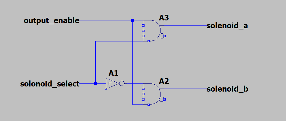
If you really want to hardware solution that disallows the uc from ever having both solenoids on you could rig up a simple inverter/enable circuit with some jellybean logic gates.

Could use a SN74HC08A for the AND gates and a SN74HC14N for the schmitt trigger inverter.

Then in software use the output enable pin to turn allow the solenoid selection to work. No matter what you do in software both solenoids cannot be on because the same selection signal is always inverted for the other.

enter image description here

\$\endgroup\$
2
  • \$\begingroup\$ There are probably all in one decoder chips that will do the same job but this really what that chip would be doing anyway. \$\endgroup\$ Commented Dec 5, 2019 at 1:11
  • \$\begingroup\$ looks good for the case of two outouts \$\endgroup\$ Commented Dec 5, 2019 at 3:25
1
\$\begingroup\$

A single output rule needs to be defined as a spec...It could be a "Priority Encoder" or a Contention Arbitrator in software when schedules selected by user collide with some round robin token ring that advances every xx minutes among the shared stack of contenders.

This would best be all be done in software.

bitcount(n): count = 0 while n > 0: count = count + 1 n = n & (n-1) return count

OR compute output Hamming Weight and correct error if not 0 or 1

(if weight>1 then fault recovery)

-

Plan B

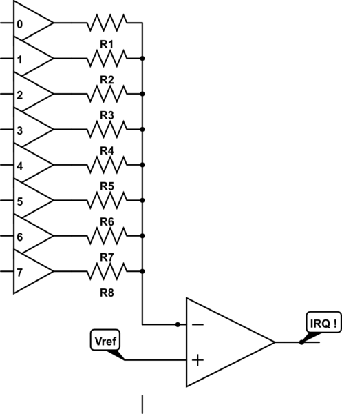
Cheap and dirty H/W IRQ if more than 2 drivers are active assuming active high out and Vdd/2 Threshold.

schematic

simulate this circuit – Schematic created using CircuitLab

Using direct output ports with a 10k Resistor array and comparator choose Vref just below when 2 outputs are high "1"

V(2)=2/(6+2) * Vdd so Vref < Vdd/4

\$\endgroup\$
4
  • 1
    \$\begingroup\$ This doesn't answer the question asked. I have what I thought were some good algorithms but I kept finding code that bypassed them accidently. The most recent involved a completely unrelated bit of code erroneously using the wrong pin for an IO operation. I'm looking for a hardware solution. (The ESP32 overloads a lot of pins with multiple functions) \$\endgroup\$ Commented Dec 4, 2019 at 23:44
  • \$\begingroup\$ So this is to circumvent stuck hardware or software faults? that you cannot probe with driver loopback? I realize it is not HW but why cant it be fixed in SW? \$\endgroup\$
    – D.A.S.
    Commented Dec 4, 2019 at 23:49
  • 1
    \$\begingroup\$ Tony, perhaps it could if I was three great programmers, or if I was less of a cheapskate and used a separate IC that was only responsible for the valves and not for the sensors and UI as well. I mean if I can't find a more basic solution I'll stick an old ATMega168 in the middle and hook it up to the ESP32 with I2C bus. I honestly thought there would be something like an xor gate that I could just wire together with some transistors however. \$\endgroup\$ Commented Dec 5, 2019 at 0:03
  • \$\begingroup\$ "I kept finding code that bypassed them accidently" if the code is properly written that shouldn't happen. As Tony Stewart said, all output commands should go through a single output routine, which enforces the rule after everything else. If you do it this way then mistakes in other parts of the code can't violate the rule. \$\endgroup\$ Commented Dec 5, 2019 at 0:15
1
\$\begingroup\$

Software solution

A simple code solution would be to use a switch construction to write specific patterns to the output port.

// There are 8 valves on port A.
switch(valveSelect){
  case 1: outputs = b00000001; break;
  case 2: outputs = b00000010; break;
  case 3: outputs = b00000100; break;
  case 4: outputs = b00001000; break;
  case 5: outputs = b00010000; break;
  case 6: outputs = b00100000; break;
  case 7: outputs = b01000000; break;
  case 8: outputs = b10000000; break;
  default: outputs = b00000000;
}
writeOut portA, outputs;

Now your code can only output those values - provided you don't write to port A anywhere else.

Hardware solution

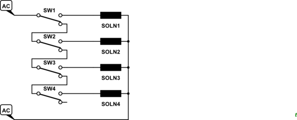
schematic

simulate this circuit – Schematic created using CircuitLab

Figure 1. Using relay changeover contacts to allow one device on only.

The electro-mechanical solution is to wire your relay contacts as shown in Figure 1. The priority is top-down. For any solenoid to be powered all the relays above it must be deenergised and all those below it have no power feed to the contacts.

\$\endgroup\$
1
  • \$\begingroup\$ That's a good one, since the relays are already there! \$\endgroup\$ Commented Dec 6, 2019 at 5:35
0
\$\begingroup\$

Frame challenge here.

You need to simplify your code to make this not possible. For instance, I suspect your "corner cases" are a result of spaghetti code slathered all over the place. Have precisely one subroutine that turns a line on (or all off). That will be the ONLY place in your code that accesses the valve hardware. (you can do a simple find/grep to assure the hardware is mentioned only once.)

The one subroutine is kept VERY simple. It receives a value from 0 to the number of valves. (i.e. 0-6 for 6 valves). 0 means off.

  • Loop through each valve, turning every one off.
  • Run down a 10 second timer.
  • Then, loop through each valve that exists, starting with 1. If it's the requested valve, turn it on; otherwise turn it off. Since no valve is numbered 0, that means calling this with a value of 0 turns them all off.

That is the only subroutine in the code that actually operates valves.

However, you should really re-assess your power supply situation so the PC doesn't reboot every time this happens. Is it a long cable run from the DC power supply to the valves? Does the computer sit at the valves and tap the same power supply cable? Most likely, voltage on that cable is dipping because of voltage drop. Run a separate power cable just for the computer so it's not affected by voltage drop on the valve power cable.

\$\endgroup\$

Your Answer

By clicking “Post Your Answer”, you agree to our terms of service and acknowledge you have read our privacy policy.

Not the answer you're looking for? Browse other questions tagged or ask your own question.