0
\$\begingroup\$

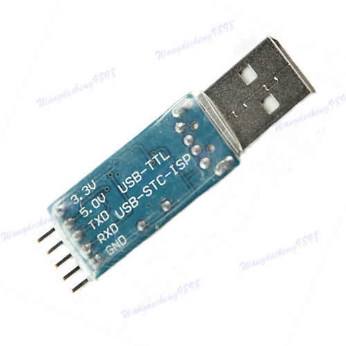
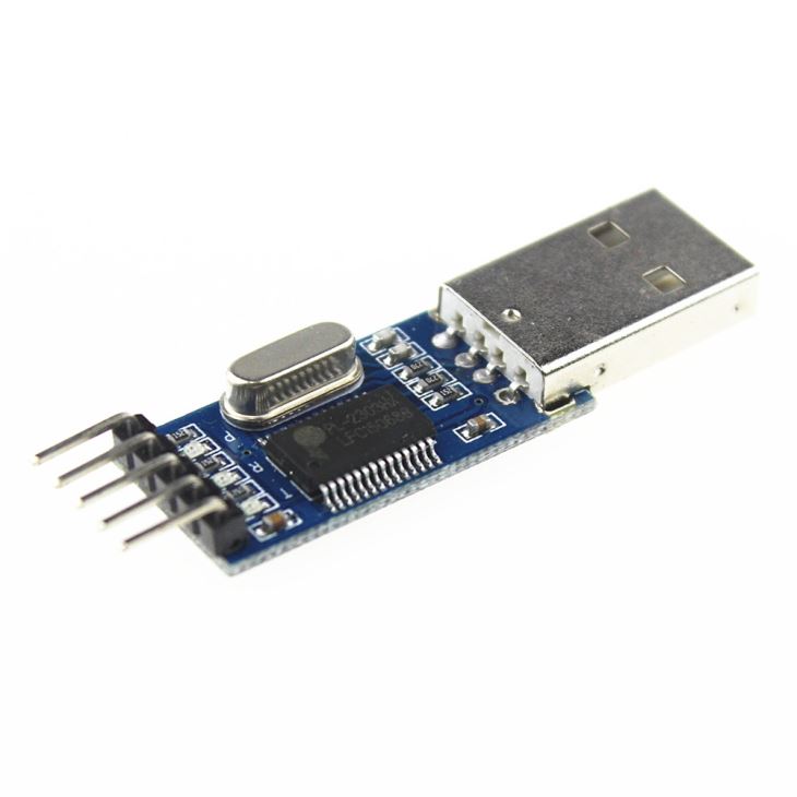
The PL2303HX is used to convert USB serial bridge controller.

I would like to connect an LED to TXD pin so that it lights when it is logic 1 and off when it is logic 0.

PL2303HX enter image description here

enter image description here

PL2303HX datasheet

I would like to consider 5mm white LED (3.3v,20mA).

Can I directly connect the LED anode to TXD with a resistor and cathode to GND.

Does it affect the baud rate?

Is it safe to draw 20mA from TXD pin?

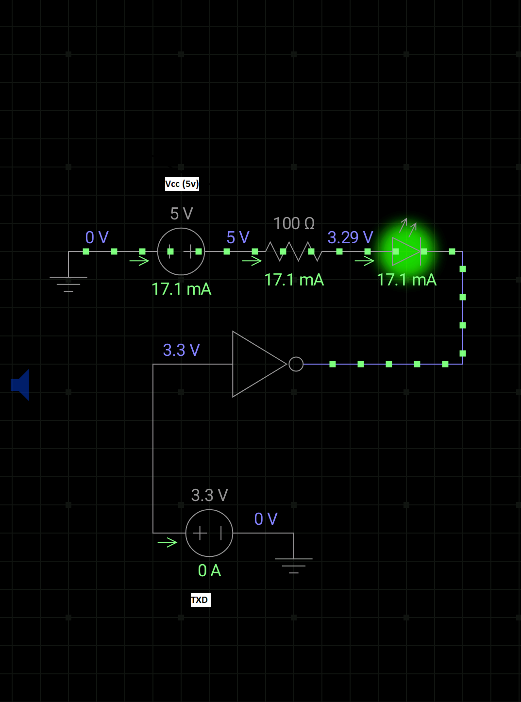
Is there a better way to light the LED using Vcc(5v) as power source and TXD as on and off like-

enter image description here

EDIT

I tried above circuit, but getting error.

I want the LED to turn off when logic 0 and turn on when logic 1. LED is powered by 5v separately. It should switch at the rate of 9600 baud rate.

\$\endgroup\$
6
  • \$\begingroup\$ what does the datasheet say about maximum current supplied by the TxD pin? \$\endgroup\$
    – jsotola
    Commented Dec 18, 2019 at 7:56
  • \$\begingroup\$ "I tried above circuit, but getting error." - what error? \$\endgroup\$ Commented Jan 18, 2020 at 11:09
  • \$\begingroup\$ @BruceAbbott I connected TXD to NOT input and output to LED cathode. I thought when TXD is logic1 it is forward bias(on) and logic 0 reverse bias(off). LED is powered by 5v Vcc and I removed pin 1 of NOT gate connection with TXD but the light glows. \$\endgroup\$
    – Sathvik
    Commented Jan 18, 2020 at 11:16
  • \$\begingroup\$ @BruceAbbott when I transfer 01111110 I get like 01010000 .I know for sure there is a problem with transmission circuit \$\endgroup\$
    – Sathvik
    Commented Jan 18, 2020 at 11:18
  • \$\begingroup\$ @BruceAbbott Actually I don't have NOT gate but I am using MC74F00N Quad 2-Input NAND Gate. Where pin 1 and 2 are connected to TXD and 3 to LED \$\endgroup\$
    – Sathvik
    Commented Jan 18, 2020 at 11:24

2 Answers 2

1
\$\begingroup\$

You need to reverse the orientation of the LED. Connect the anode of the LED to the output of the NOT gate, then connect the cathode to the resistor and the other end of the resistor to ground. The LED will light when the output of the NOT gate is high, which is when TX is low.

\$\endgroup\$
7
  • \$\begingroup\$ I want to draw power from Vcc not from TX. I want TX as switch logic 0 off,logic1 on \$\endgroup\$
    – Sathvik
    Commented Jan 18, 2020 at 13:16
  • \$\begingroup\$ 'Connect the anode of the LED to the output of the NOT gate, then connect the cathode to..' I tried to emulate but did not work. \$\endgroup\$
    – Sathvik
    Commented Jan 18, 2020 at 13:17
  • \$\begingroup\$ You will be drawing power from the NOT gate, which is drawing its power from Vcc. \$\endgroup\$ Commented Jan 18, 2020 at 14:02
  • \$\begingroup\$ ya, got it but how much voltage does logic 1 is produced by MC74F00N. Is it 5v \$\endgroup\$
    – Sathvik
    Commented Jan 18, 2020 at 14:08
  • \$\begingroup\$ Well, you didn't tell us you were using a 74F00. That would have been helpful information. Use an actual CMOS inverter instead. \$\endgroup\$ Commented Jan 18, 2020 at 14:13
1
\$\begingroup\$

Yes, there is a better way: A transistor.

A transistor can be used to switch a strong signal (high LED current from +5V supply) with a weak signal (TXD output pin) without degeneration of the weak signal.

You could use a MOSFET, but they often have high gate capacitance which burdens/degrades the TX signal. It would be better to use a bipolar transistor, but there you need an additional bias resistor for the base.

\$\endgroup\$

Your Answer

By clicking “Post Your Answer”, you agree to our terms of service and acknowledge you have read our privacy policy.

Not the answer you're looking for? Browse other questions tagged or ask your own question.