1
\$\begingroup\$

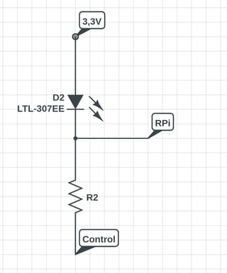
I have a PCB which I am trying to connect to a Raspberry Pi. The PCB has some LEDs which indicate some status. Each LED anode is connected to 3.3 V while its cathode goes through a resistor to ground.

I have soldered some wires to the negative side of the LEDs, as that was the only accessible point I could safely solder something to. However, this means that on that point, when the LED is emitting, I get 1.5 V more or less, and when its not emitting, I get 3.3 V.

I have tried to read those values directly in the Raspberry, hoping it was low enough to consider it a logic LOW but it's not.

How could I convert an LED voltage of LIT=3.3 V and OFF=1.5 V to corresponding logic voltages of 3.3 V and 0 V?

My circuit will be similar to this. The control can be 0 V or 3.3 V, depending on some logic or an IC on the PCB I am trying to connect to the Pi.

enter image description here

\$\endgroup\$
7
  • \$\begingroup\$ Tell us which version of the RaspBerryPi you are using and which type of library to use the GPIO-pins. If you are using the RPi4 and WiringPI, then there is a bug, the PullUp are always activated, it is impossible to deactivate them. So you have to use an other library. \$\endgroup\$
    – MikroPower
    Commented Mar 20, 2023 at 1:07
  • \$\begingroup\$ I am using a Pi 3 Model B an RPi-GPIO \$\endgroup\$
    – jjcasmar
    Commented Mar 20, 2023 at 1:08
  • \$\begingroup\$ Then you should measure the voltage at the input pin while your PCB is not connected. If it is 3.3V, then the pullup is activated. If you show your code, then we can help you with it. \$\endgroup\$
    – MikroPower
    Commented Mar 20, 2023 at 1:17
  • \$\begingroup\$ The voltage when the PCB is not connected is fine, I read 0 when nothing is connected to the RPi pin. The issue I have is that the voltage on the PCB where I am reading is 1.5 approx, and the RPi is considering that as a high voltage. \$\endgroup\$
    – jjcasmar
    Commented Mar 20, 2023 at 1:19
  • \$\begingroup\$ What you wrote, this sounds like a pullup somewhere. Maybe on your PCB. It is impossible that the gpio pin could be on 3.3V in this configuration, because of the 1.8V voltage drop over the LED. 3.3V is only possible if there is a pullup resistor. Look again or do it in the morning if you are refreshed. \$\endgroup\$
    – MikroPower
    Commented Mar 20, 2023 at 1:26

1 Answer 1

1
\$\begingroup\$

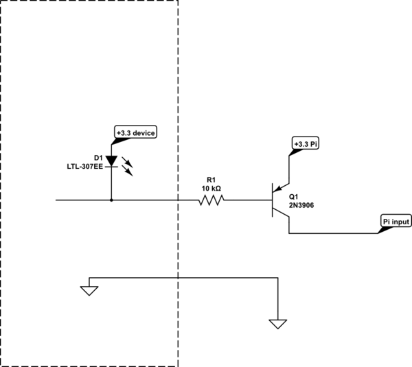
Here is an easy way to do this, though not exactly what you are asking for:

schematic

simulate this circuit – Schematic created using CircuitLab

You should enable the pull-down in the Raspberry Pi input or add a resistor to ground such as 10kΩ

The input will be high when the LED is on (or power is off in the remote device) and low when the LED is off and power is on in the remote device.

Just about any small-signal PNP transistor can be used.

It's possible you may have to add a pull-up resistor across D1 depending on what exactly is driving it.

\$\endgroup\$
5
  • \$\begingroup\$ I am not completely sure I understand your circuit. I am adding a circuit to mine in case it was not clear \$\endgroup\$
    – jjcasmar
    Commented Mar 20, 2023 at 1:08
  • \$\begingroup\$ This will not work. Simply because he said that he have 3.3V at the pin. +3.3V---LED---pin---resistor---GND , this means that the internal pullup of the RPI is activated and your transistor would be always activated. Normally the voltage would be 3.3V-U_LED=1.5V or 0V. So he have the RPi pullup-problem. \$\endgroup\$
    – MikroPower
    Commented Mar 20, 2023 at 1:11
  • \$\begingroup\$ @MikroPower then make it a pull-down instead? \$\endgroup\$ Commented Mar 20, 2023 at 1:15
  • \$\begingroup\$ @user253751 - With the Pi4 I had the problem, this did not work with WiringPi. He is using the RPi3, so this should be not a problem. Possibly he have accidentally activated the pullup. \$\endgroup\$
    – MikroPower
    Commented Mar 20, 2023 at 1:20
  • \$\begingroup\$ I didn't say I have 3.3V at the pin. I said that when the led is on, it is 3.3V at the pin, and the RPi reads True, but when the led is off, the pin is at 1.5 V (3.3V - LED drop), and the RPi still reads True \$\endgroup\$
    – jjcasmar
    Commented Mar 20, 2023 at 1:21

Your Answer

By clicking “Post Your Answer”, you agree to our terms of service and acknowledge you have read our privacy policy.

Not the answer you're looking for? Browse other questions tagged or ask your own question.