0
\$\begingroup\$

Recently I bought an old musical keyboard (a Casio HT-3000). It came with a PSU, and when it arrived I plugged it in without paying too much attention, and... nothing but a burning smell. I quickly unplug and look at PSU ... seems they sent me the right voltage, but wrong polarity (Casio had -ve on the centre pin of their power supplies at that time).

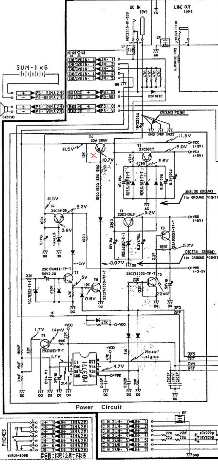
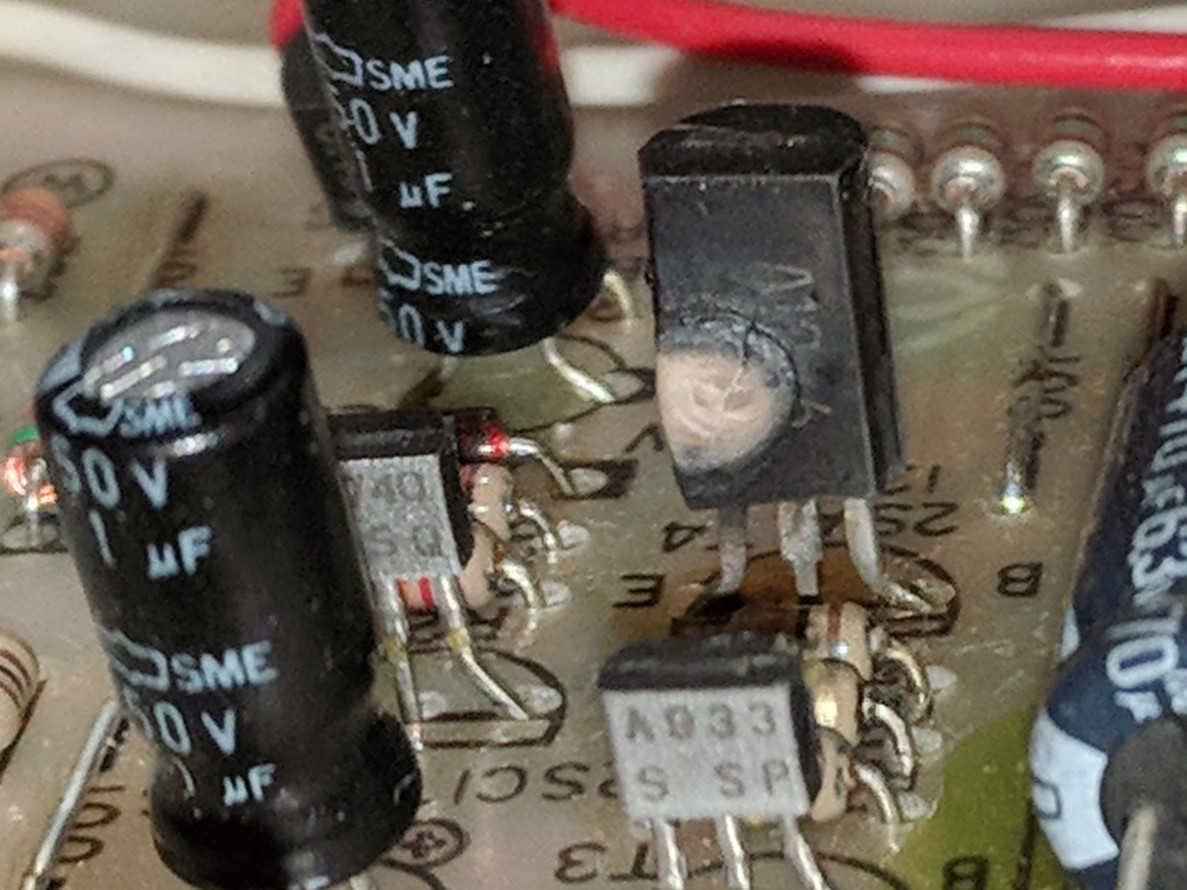
I've found the schematics, and inspected the board. From inspection it's obvious that transistor T4 was the source of the burning smell, so that obviously needs to be replaced. Not sure if there is anything else fried less-obviously.

T4 is a 2SA1286H. Now I've found a vendor for a 2SA1286 (datasheet), but can't find the h version. As far as I can tell, the H version had a higher hFE (1200, as compared to 400-800 in the non-h version).

  • Will the non-h version of this transistor suffice as a replacement (I assume not). If not, what could I use instead?
  • What is the purpose of T4 in this circuit?
  • Does it look likely that other components will have been damaged?

Thank you for any help.

Unhappy transistor Unhappy transistor

Schematic (x marks T4) Schematic (x marks T4)

\$\endgroup\$
6
  • \$\begingroup\$ higher hFE (1200mA, as compared to 400-800mA in the non-h version). hFE (or \$\beta\$, the current amplification) isn't expressed in mA. It has no unit since it is a ratio of currents. The lower hFE should not matter, if it does then the designer was asking for trouble as hFE isn't a tightly controlled value, it can be very different on the next transistor of the same type. So a good design will work even with a much smaller (or larger) hFE. You have the schematic and there are voltages indicated so measure them. A significantly different voltage indicates broken components. \$\endgroup\$ Commented Feb 20, 2020 at 10:20
  • \$\begingroup\$ @Bimpelrekkie Ooops, thanks. I'll edit the question. Thanks for the info. \$\endgroup\$
    – UpTheCreek
    Commented Feb 20, 2020 at 10:33
  • \$\begingroup\$ /APO low turns off T5 and thus T4. It's still (so far) not obvious why it should voltage regulate. \$\endgroup\$
    – Russell McMahon
    Commented Feb 20, 2020 at 15:37
  • \$\begingroup\$ @Bimpelrekkie I can't see why T4 acts as a regulator rather than an on/off switch. Can you see any obvious feedback path? | The whole cct looks vastly 'overengineered'. \$\endgroup\$
    – Russell McMahon
    Commented Feb 20, 2020 at 15:38
  • \$\begingroup\$ @RussellMcMahon I can't see what T4 is doing either. I also thought that it looked like a regulator but later changed my mind as indeed the feedback seems to be missing so it looks more like a switch indeed. T1 and T2 are the regulators. \$\endgroup\$ Commented Feb 20, 2020 at 20:41

2 Answers 2

1
\$\begingroup\$

Will the non-h version of this transistor suffice as a replacement (I assume not).

Probably OK.
It's not apparent that the beta difference would be critical.
The 4 series base drive resistors is a strange arrangement - and it appears that there MAY be only 3 in the photo. Maybe #4 is somewhere else.
They are either 1500 or 150 Ohms.
Even with 150 Ohms - power dissipation per resistors is V^2/R/4 = about 10^2/(4 x 150) /4 =~ 40 mW.
Current at 150 Ohms x 4 = I=V/R = 10/600 ~= 16 mA.
Even at a beta of 100 Ic = Beta x Ib = 1600 mA !!! = unlikely.
(Ic rated = 1.5A).

If not, what could I use instead?

Probably no need, but any suitably high current highish beta pnp should do.

A BC327-40 may suit. (-40 version is highest beta bin). PNP, only 800 mA but probably adequate. Beta is 25-630 (400 typical) at 100 mA. Rth = 200 C/w - so depends on current but probably not 100 mA - but MAY be. Datasheet here

Or a larger package - TO220 safe.
TO126 closer to original size but these are usually older low spec parts.
2 x BC327-40 in parallel is an option. Keep somewhat separate physically for airflow.

What is the purpose of T4 in this circuit?

It's either and on/off switch or part of a voltage regulator. I can't see a feedback path that makes the regulator function make sense.
It drops 11.5-9 = 2.5V.
Rated max dissipation = 900 mW Nice data sheet considering but there seems to be no Rthja.
At 900 mW and 2.5V drop you could handle I = P/V = 0.9W/2.5V = 280 mA.
Odds are it's rated for full dissipation in free air so say 100 °C rise worst case
So Rth = T/P = 100/0.9 ~= 110 °C/W.
The TO92 BC327-40 is rated at 200 °C/W so the physically rather larger strange-old-galumphing package looks liable to be closer to 100 °C/W

Does it look likely that other components will have been damaged?

Hard to be sure.
T1, T2 are good candidates as fed from T4. Less likely T3. Less again T5.

What looks like Te at 3SC2113? at kleft middle as it's a power controller.

Other quite possible BUT may be OK.


Only vaguely relevant aside:

Long long long ago (40+ years) I applied ?120V? to the 5V rail of a Motorola MC6802 "D2 kit). Much died. The saving grace was that all ICs were socketed. I replaced the lot from another system then back substituted until there was a failure. In due course all the dead ICs were found that way. All that died were ICs with power drive capabilities (6821 port ICs etc). Evidently what could sink current did, and died.

\$\endgroup\$
4
  • \$\begingroup\$ Great info, thank you for taking the time. Ok then, I'll replace that T4 with the non-h version and go from there. Will report back here with results. \$\endgroup\$
    – UpTheCreek
    Commented Feb 20, 2020 at 10:52
  • \$\begingroup\$ And nice anecdote - this dev kit? : en.wikipedia.org/wiki/MEK6800D2#/media/… \$\endgroup\$
    – UpTheCreek
    Commented Feb 20, 2020 at 12:36
  • 1
    \$\begingroup\$ @UpTheCreek That's the one. 15 socketed ICs there (incl xtal osc). Memory says all mine were. Maybe not. Still in my e-dungeon 40+ years on! :-). || Wrote in machine language (no assembler). Hand assembled menmonics to code. Calculated relative jumps manually. Up hill both ways cardboard box snow ... :-). | \$\endgroup\$
    – Russell McMahon
    Commented Feb 20, 2020 at 15:11
  • \$\begingroup\$ So, replacing T4 did the trick :-) At least, no problems so far. Thanks again for your help. \$\endgroup\$
    – UpTheCreek
    Commented Mar 6, 2020 at 9:52
1
\$\begingroup\$

I had the same problem and also T6 was OFF.The zener diode at Base of T6 was OFF' I replaced T6 with BC238C (C means high hFE 400-800) zener is 4V or 5,1V and T4 with BC560C. If the problem goes on the you can put an external switching power supply at collector (C) of T4. T4 must be out.You can fix the fis at the side. Good luck!

\$\endgroup\$

Your Answer

By clicking “Post Your Answer”, you agree to our terms of service and acknowledge you have read our privacy policy.

Not the answer you're looking for? Browse other questions tagged or ask your own question.