I have a KUS SSS Water level sensor for my RV that I would like to have trigger a NO 12v solenoid valve to turn off when my tank has reached full (and ideally also sound a little piezo). The sensor ranges from 240 Ω empty to 33 Ω full. I'd like to trigger at about 50 Ω. I'm wondering what would be the simple circuit to make this happen?
2 Answers
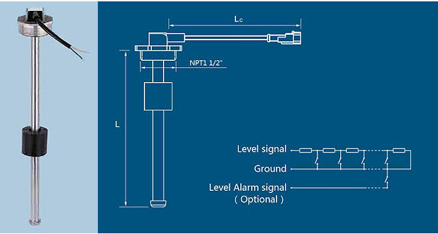
Figure 1. Extract from the datasheet.

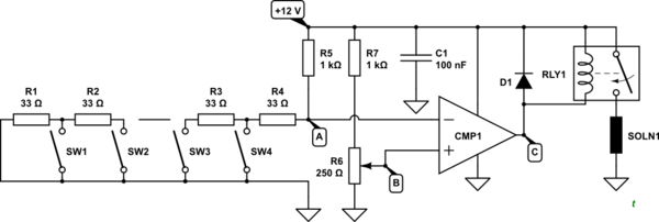
simulate this circuit – Schematic created using CircuitLab
Figure 2. A sample circuit.
How it works:
- The sensor has a series of resistors with reed switches connecting the nodes of the resistor chain to ground. The higher the float goes the more of the resistor chain is bypassed.
- R5 controls the current into the resistor chain (R1 to R4). The maximum current will be about 12 mA from the 12 V supply.
- With all switches open you'll have 240 Ω between A and GND. This along with R5 will form a potential divider so the voltage at A will vary from \$ \frac {240}{1000 + 240}12 \text V \$ when empty down to close to \$ \frac {33}{1000 + 240}12 \text V \$ when full.
- R6 is potentiometer to set the trip point. By adjusting the wiper the level sensing threshold voltage, B, can be adjusted across the same range as the sensor.
- CMP1 is a comparator. If the sensor voltage goes above the threshold voltage the output, C, will be connected to GND by CMP1 and RLY1 will turn on.
- D1 protects the comparator from the inductive kick-back of RLY1 when it is switched off.
If the logic of CMP1 is the reverse of what is required then swap the + and - inputs.
See my answer to https://electronics.stackexchange.com/a/483708/73158 for a similar design.
I think that an Arduino is usually a good solution in these kind of projects. For detecting the level use the analog input, make a voltage divider with a fixed resistor and your sensor, determine the voltage at witch you want to trigger the valve, then use a digital output to activate the valve, of course not directly, because it's 5V, use a transistor circuit. If you are not very familiar with programming, don't worry you can find ready scripts to mix together to make it work. I am sorry that this doesn't involve schematics and point to point explanation as some others answers here, but I hope that I could help with an idea.
-
\$\begingroup\$ yes arduino is an easy option, but want to avoid using a microcontroller \$\endgroup\$ Commented Mar 4, 2020 at 21:16

