4
\$\begingroup\$

Following is my water tank representation, im controlling the water inlet pump using one water level sensor, apart from that i have already designed the sensor circuit for HIGH & LOW level only (due to minimum hardware). Sensor circuit works very well. Now im stuck at logic design stage, because as shown in fig. 1V = Empty Tank & 5V = Full tank. enter image description here I want to turn on the water pump @1V to upto reach at 5V level, after that turn off the pump till sensor sense the 1V.
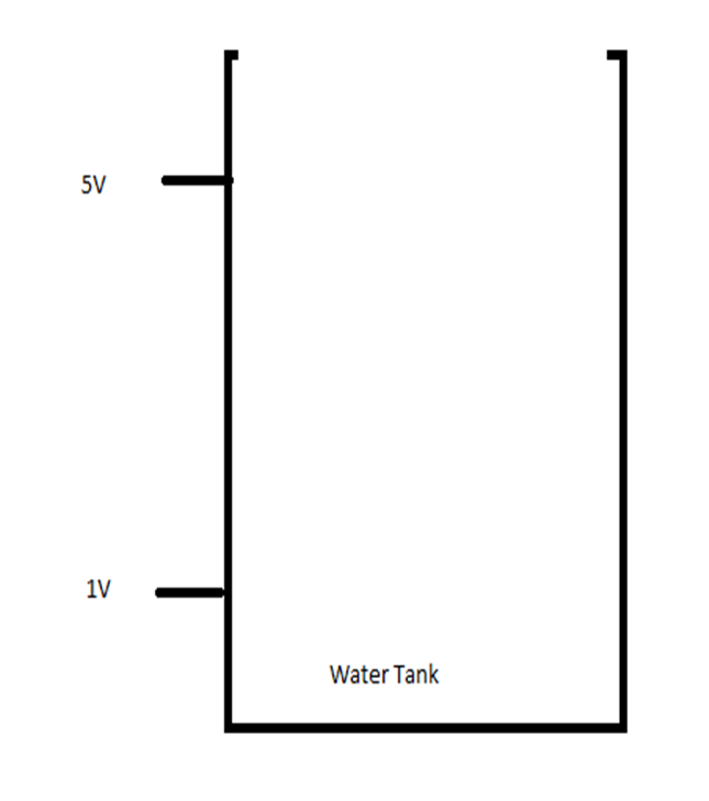
Note - I have tried Window comparator circuit it work fine during water filling from 1V to 5V, but it suddenly start the pump at 4.5V (I strictly want to make turn on the pump only @1V. also i have tried NAND gate ic , but it also works same as Win So anyone suggest me any logic gate or any other ckt for this?

\$\endgroup\$
4
  • 1
    \$\begingroup\$ Logically you want a set/reset flip flop, using <1V as your set, and 5V as your reset. Then you just need to condition the output of your sensor to produce the two digital signals. If you're finding the signals trigger at the wrong voltage, that sounds like an issue with your circuit, so please add this. \$\endgroup\$
    – LordTeddy
    Commented Apr 6, 2023 at 11:19
  • 1
    \$\begingroup\$ @Bhushan It would be helpful if you show the circuit that you have tried that does not work correctly. You may learn more and we may better understand your issues if we know what you have tried. If you just want a circuit that works and not advice on what is wrong there are many circuits available on ghe internet. Our aim here is to assist you both with your requirement and to learn how to do it better next time. \$\endgroup\$
    – Russell McMahon
    Commented Apr 6, 2023 at 11:35
  • \$\begingroup\$ Once the water has filled up to 5V, what causes it to reduce down to 1V? \$\endgroup\$
    – jonathanjo
    Commented Apr 6, 2023 at 12:38
  • \$\begingroup\$ @jonathanjo when i used tank water for house use. \$\endgroup\$ Commented Apr 6, 2023 at 12:50

1 Answer 1

9
\$\begingroup\$

I have tried Window comparator circuit it work fine during water filling from 1V to 5V, but it suddenly start the pump at 4.5V

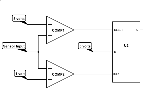
A window comparator will do this because it doesn't have hysteresis. You need hysteresis between the upper and lower voltage "action" levels. You could use a single comparator with positive feedback to give hysteresis but, the resistor values can be a little fiddly to calculate so, my preferred approach is to use a dual comparator driving a D type flip-flop with a reset circuit.

The flip-flop is commonly available in a single SMD package or dual package: -

schematic

simulate this circuit – Schematic created using CircuitLab

If the sensor output becomes less than 1 volt then, COMP2's output will trigger the flip-flop (via CLK) and, because D is set to logic 1 level, the Q output will be set.

The Q output then drives your pump (via appropriate circuitry) until the sensor output hits 5 volts. At this point COMP1 resets the flip-flop and turns the pump off. When the water level drops sufficiently, COMP2 will re-trigger the flip-flop to restart the pump.

I might be tempted to add some water overflow protection circuit as a back-up against a single failure of the circuit.

\$\endgroup\$
0

Your Answer

By clicking “Post Your Answer”, you agree to our terms of service and acknowledge you have read our privacy policy.

Not the answer you're looking for? Browse other questions tagged or ask your own question.