0
\$\begingroup\$

I have UpSquared board for an embedded system. I have a main power supply(battery) to feed it and I also have a back-up battery for some situations.

For example, something happened and main battery is not able to feed my board anymore. My question is that how many minimum time is required to switch from main battery to back-up battery because I don't want my board to shut down. Or how can I calculate that time?

Edit:

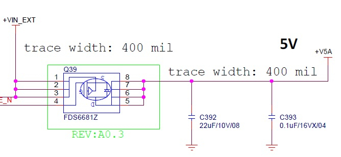
Here is schematic of my entrance power of my board: My dV is 5V and I is 4 Amper

enter image description here

\$\endgroup\$
3
  • \$\begingroup\$ What do you mean by battery failure? Disconnection or drained? \$\endgroup\$
    – User323693
    Commented Mar 6, 2020 at 8:40
  • \$\begingroup\$ Yes, disconnection I mean. \$\endgroup\$ Commented Mar 6, 2020 at 8:43
  • 1
    \$\begingroup\$ Using only the on-board capacitors, miliseconds at best. \$\endgroup\$
    – winny
    Commented Mar 6, 2020 at 9:02

4 Answers 4

3
\$\begingroup\$

When the battery is disconnected, the load will have to only rely on the capacitors on the board. The voltage will drop at a rate depending on the total capacitance available.

If allowed drop on voltage is dV, then time will be
Time = dV* C/I
Where I is the load current.

Share the actual values of load current, allowed dip and capacitance available, so that we can see how much will be the time.


Edit 2:

Example:

Load current - \$800 mA\$
Change in voltage allowed = \$5 V\$
Capacitance available: 4\$70 mF\$

calculated time will be = \$293.75 ms\$

\$\endgroup\$
10
  • \$\begingroup\$ Thanks for your answer. My board load current is 4A~6A(generally 5A) but I have no idea about the capacitors on the board. When I searched, I also couldnt find something about it. Can you suggest something how to go on? \$\endgroup\$ Commented Mar 6, 2020 at 9:00
  • \$\begingroup\$ dV is 5 volt, I is 4 Amper but I have no idea how to choose capacitor. Can I use power supply capacitors? \$\endgroup\$ Commented Mar 6, 2020 at 9:07
  • 1
    \$\begingroup\$ Yes. The. Capacitors which are there at the point where you connect main supply \$\endgroup\$
    – User323693
    Commented Mar 6, 2020 at 10:02
  • \$\begingroup\$ Okey then, I ll try to find out my capacitors. My last request is that can you assume a capacitor value and calculate the time to be able to see how the calculation is. And you may edit your answer. After that I ll accept your answer. Thank you very much. \$\endgroup\$ Commented Mar 6, 2020 at 11:28
  • 1
    \$\begingroup\$ 470mf, do you mean "milli" like about 0.5 farad? That's a big cap. You'll pay a price for such a big cap in inrush current everytime you power up. You may also have weird problems because that will slow the natural power-down of the system. \$\endgroup\$ Commented Mar 6, 2020 at 20:41
1
\$\begingroup\$

Assuming that the board in question has a SMPS (Switch Mode Power Supply) at the input (due to efficiency for example), it will act as a constant power load. Meaning, that in case of a supply interruption it will be supplied mainly by the output capacitors of the main power supply, and the time taken for reaching a specific voltage level at the input of the board is given by:

$$ t = \frac{C_{MAIN,PS} \cdot (V_{B,NOM}^2 - V_{B,MIN}^2 )} {2\cdot P_{BOARD}} $$

Where:

$$V_{B,NOM}$$ is the nominal voltage of the board

$$V_{B,MIN}$$ is the minimum allowed voltage, before triggering and the backup supply

\$\endgroup\$
2
  • \$\begingroup\$ Thanks for your answer. What is Pboard here? I am also not sure my board has a SMPS or not. \$\endgroup\$ Commented Mar 6, 2020 at 9:03
  • \$\begingroup\$ Pboard is the maximum power consumption of your board. It is probably in the datasheet. In your case is 5V * 6A = 30W \$\endgroup\$
    – vtolentino
    Commented Mar 6, 2020 at 9:09
1
\$\begingroup\$

You don't need to switch

Since your system is DC, You can have an electronic version of an "overrunning clutch", i.e. The gadget that lets a helicopter's other engine(s) keep turning the rotor when one quits. This is called a diode, and you put one above each power source. The one with the higher output voltage (allowing for the diode's own voltage drop) powers the device. The switch is instantaneous.

Diodes have a relatively constant voltage drop through them, you are paying that voltage drop "fee" at all times. So favor diode types with very low voltage drop, e.g. Schottky. I can't think of a zero-cost way to do this; even a mechanical relay needs to be held actuated by the primary supply.

\$\endgroup\$
2
1
\$\begingroup\$

It may fully be there are no big capacitors on the board that is designed to be fed by external power supply. Fortunately if you connect the spare battery via diode, you only need enough time for that diode to open. Conventional rectifier diode may have the switching time of somewhat 20 microseconds only (source) so you only need a small capacitor of few μF, or even existing (unknown) capacitors on the board may be sufficient. Some capacitor is probably required as even transient power out may reset the board (read here for more). Fast recovery diodes are available that can do this faster.

\$\endgroup\$
1
  • \$\begingroup\$ I am planning to use Schottky diodes for quick reverse recovery time as suggested by @Harper-ReinstateMonica but can I find a appropriate Schottky for my voltage values? \$\endgroup\$ Commented Mar 11, 2020 at 8:21

Your Answer

By clicking “Post Your Answer”, you agree to our terms of service and acknowledge you have read our privacy policy.

Not the answer you're looking for? Browse other questions tagged or ask your own question.