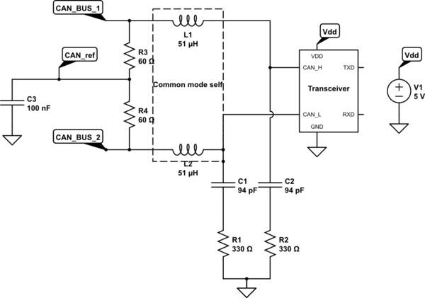
Here is the circuit :

simulate this circuit – Schematic created using CircuitLab
I suppose the circuit is used for filtering the noise coming from the CAN Bus. According to the transceiver datasheet between the microcontroller and the filter, "High Speed (up to 1 Mbit/s)", the maximal CAN speed is 1 MBits. First question, does the CAN protocol need a filter ? The can protocol is said to be robust and working in harsh environnement. So what is an harsh environnement... I have no informations about the operating environnement of this CAN and filter.
I do not really know how does the CAN physically works. According to the informations that I found, I did the approximation that the input waveform coming from the bus was a square wave. So the input waveform at the filter stage is a square waveform whose the frequency is 1 MHz (worst case). I do not know if it lower or not... According to Fourier, there is a lot of (infinite) harmonics into a square wave, so obviously the filter will have an impact on the input waveform. The filter should be designed to have a high attenuation on noise and a very low attenuation on the waveform. Even if I do not consider the noise, the filter will have a high impact on the input waveform... Indeed, the resonant frequency is equal to 2.29 MHz, Q is equal to 2.23 > 1/2 so the filter is underdamped. I would like to have your opinion about this filter. Is it well designed ? Under which conditions ? I can understand that the filter have to be underdamped as to increase the rise time and fall time of the waveform. Nevertheless it rings ... Do you think that those oscillations can introduce error when decoding the signal coming from the bus ? In other words, wouldn't be better if the filter was not here ? Wouldn't be better if the resonant frequncy would be higher than 2.2 MHz ? There would be less attenuation on low frequency noise but the filter would less modify the input waveform.
It will also deform the waveform coming from the transceiver and going to the bus.
By the way, what is the purpose of using a common mode inductance rather than two separates inductances ? it means that when one input (CAN_High) of the transceiver is sourcing current the other (CAN_Low) is sinking current for example and inversely ?
Thank you very much !

