0
\$\begingroup\$

enter image description here

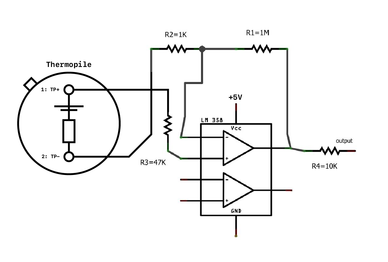
I'm trying to make a circuit for a physics experiment where I measure the voltage output from a thermopile.

Because the raw output voltage is in millivolts, I need to use an op-amp circuit to amplify the voltage. The circuit above should amplify it by a factor of 1000, as R1/R2 = 1000.

I connected a voltmeter between the output after R4 and the TP- pin to measure this amplified voltage, but it reads ~0V and doesn't change so I think I have the voltmeter wired to the wrong bits. I know the thermopile works, because I've measured it to output a few millivolts by itself.

I'm new to circuits and have been following diagrams to set this up. Would anyone be able to let me know where the voltmeter should actually be, or if the circuit is wrong?

Datasheets:

\$\endgroup\$

3 Answers 3

2
\$\begingroup\$

You need to ground the negative terminal of the thermopile.

The LM358 is a single-supply op-amp and it will work with a 5V supply, however the output voltage will be limited to about 0-3V over temperature and a bit more than that typically.

The LM358 also has a typical offset voltage that can be as much as your entire signal, so it's not a great choice for this application. Ideally get a better op-amp or at least give the op-amp a negative supply and trim the offset out. The sample circuits on the datasheet show a pseudo-ground created by a Zener diode to provide some offset.

If the particular op-amp sample you have happens to have a large negative offset you'll get about 0V out pretty much regardless of the thermopile output, even when it's connected properly. If it's a positive offset you'll see a large output voltage (as much as 3V) even without a thermopile signal.

You should also match the impedances seen by the inputs and add some low pass filtering to an amplifier with such a high gain. For example, a 100nF capacitor across the 1M and another 100nF from the non-inverting input to ground.

A suitable amplifier would be the NCS325SN2T1G which costs a bit more than an LM358 (32 cents in 100's) but performs much better in this application (low supply current, rail-to-rail input and output, microvolt offset). Don't forget that if you need negative output you need to give it a negative supply (and that particular op-amp can only handle 5.5V so something like -1 + 4V.

\$\endgroup\$
3
  • \$\begingroup\$ Thank you. I followed this tutorial which uses the LM358... guess it's just not a great choice. However, before I buy another amp, I just want to see if I can get my circuitry to work at all, i.e. see amplified voltage change. I've connected the TP- pin to the 5v supply ground, and connected my voltmeter between the output and the same ground, but the voltage still doesn't change. I know you said it might not change by much, but it doesn't at all. Do I need to 'complete' the circuit by connecting the output wire to something else? \$\endgroup\$ Commented Apr 18, 2020 at 7:44
  • \$\begingroup\$ Try another chip or the other amplifier in the chip. \$\endgroup\$ Commented Apr 18, 2020 at 12:58
  • \$\begingroup\$ Also open the input from the thermopile and the op-amp output should go to 4V or so. \$\endgroup\$ Commented Apr 18, 2020 at 13:13
1
\$\begingroup\$

If you want to measure the unloaded voltage from the pile, the best configuration to do that is called an instrumentation op-amp. Basically, it's 3 op-amps wired as a differential op-amp.

More here: https://www.allaboutcircuits.com/textbook/semiconductors/chpt-8/the-instrumentation-amplifier/

With such a low input voltage, input offset becomes a problem. To address this, there are specialty instrumentation op-amps that have very low input offset, some using a technique called chopper stabilization. Lucky for you, they're available as a chip, like this one: https://www.analog.com/media/en/technical-documentation/data-sheets/1100fc.pdf

This ADI device has a fixed gain of 10 or 100. With a gain of 100, this should be easy enough to measure with a voltmeter, which will typically have 3 or 4 significant figures.

The AD620 is another choice. More here: https://www.analog.com/media/en/technical-documentation/data-sheets/AD620.pdf

And it looks like you can buy an AD620, mounted on a board and ready to go. Darn cheap, if you believe eBay: https://www.ebay.com/itm/DC-Microvolt-Milivolt-Voltage-Amplifier-Board-AD620-Signal-Module-Adjustable-New-/222923153913

\$\endgroup\$
2
  • \$\begingroup\$ Thank you. I followed this tutorial which uses the LM358... guess it's just not a great choice. However, before I buy another amp, I just want to see if I can get my circuitry to work at all, i.e. see amplified voltage change. I've connected the TP- pin to the 5v supply ground, and connected my voltmeter between the output and the same ground, but the voltage still doesn't change. I know you said it might not change by much, but it doesn't at all. Do I need to 'complete' the circuit by connecting the output wire to something else? \$\endgroup\$ Commented Apr 18, 2020 at 7:44
  • \$\begingroup\$ The LM358 needs to be connected as a differential amp. More about this topology here: electronics-tutorials.ws/opamp/opamp_5.html In this tutorial, I'd recommend R1/R2 at 1K, and R3/R4 at 100k for a gain of 100. Don't try to get a gain of 1000 out of an LM358. \$\endgroup\$ Commented Apr 18, 2020 at 19:47
0
\$\begingroup\$

first thing the LM358 op amp is not suited for this application because of the thermopile sensors can give negative voltages, these opamp cannot pickup this.so its better to go with a better rail to rail opamp.I am trying to make a breakout board for a thermopile sensor for the past 2 months.i had tried lm358,AD620 opamp and everthing but it did not give a readable value.So its better to go with an opamp like LMC6482 which is a cmos rail to rail opamp.

\$\endgroup\$

Your Answer

By clicking “Post Your Answer”, you agree to our terms of service and acknowledge you have read our privacy policy.

Not the answer you're looking for? Browse other questions tagged or ask your own question.