0
\$\begingroup\$

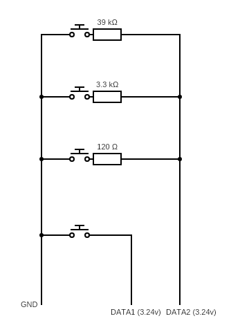
I would like to control my PC monitor. After disassembly I found the control buttons are implemented like this (just more data line and buttons)

control buttons circuit

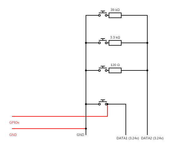
I would like to control it (with ESP2866) With the first button which is alone in a DATA line 1 there is no problem I just simply pull down with one of the GPIO like this and it is working flawlessly (I don't use any resistor because expecting in the other side there is)

enter image description here

With Data line 2 I’m having trouble with the same approach the button with the smallest resistor is triggered from other button. I try to use resistor, transistor but it just got worse.

Please note ESP is working a bit higher voltage than 3.24v it is 3.26v Also connected the ground wires

I wonder how should I try to interface with this?

Thank you

\$\endgroup\$
3
  • \$\begingroup\$ How is your ESP pins configured? Is it push-pull output, or open-drain? \$\endgroup\$
    – Justme
    Commented Jun 8, 2020 at 19:59
  • \$\begingroup\$ I am using Tasmota with Inverted Relay option \$\endgroup\$
    – ebalcsk
    Commented Jun 8, 2020 at 20:20
  • \$\begingroup\$ Ok, great, but what does it mean regarding how the pin is configured? We are not aware how each hobbyist framework operates under the hood, be it Arduino, Tasmota or whatever is the best next year. \$\endgroup\$
    – Justme
    Commented Jun 8, 2020 at 20:29

3 Answers 3

1
\$\begingroup\$

Use an NPN transistor or small signal N channel MOSFET. The GPIO drives the base/gate (the NPN transistor includes a series resistor with the base). The collector/drain is connected to the resistor side of the switch. Have one sub-circuit like this for each of the switches.

You could also use an IC chip that has open collector/drain output for buffering the GPIOs to the switch connections.

\$\endgroup\$
3
  • \$\begingroup\$ Thank you Michael. 2sc2120 is good for the job? \$\endgroup\$
    – ebalcsk
    Commented Jun 8, 2020 at 20:29
  • \$\begingroup\$ @ebalcsk - The 2SC2120 should work for you if you want the TO-92 type leaded package. \$\endgroup\$ Commented Jun 9, 2020 at 0:34
  • \$\begingroup\$ Thank you everybody for the help! With 2sc2120 i was able to make his work :). Un fortunately Tasmota code is pretty huge, so it would taken way more time for me to modify the code \$\endgroup\$
    – ebalcsk
    Commented Jun 9, 2020 at 13:46
0
\$\begingroup\$

You can make this circuit independent of power voltage of ESP, it could be 25 volts. You hook up exactly there, your GPIO pins are all just INPUTS - that makes them open line. They look like an unpressed button to the system. And when you "press" - you OUTPUT LOW them. Releasing it - making INPUT again. See if you may want to make it LOW for a few milliseconds. I think it should work fine like that.

I had an idea to wire up an MCU to a display panel like that for a while now, maybe will finally get my hands on it.
P.S. I assumed to did output high when unpressed, you didn't clearly indicate that

\$\endgroup\$
0
\$\begingroup\$

If a GPIO is wired to Data1, then wire the other GPIO's as follows:

  • Next GPIO to 120Ω to Data2
  • Next GPIO to 3.3kΩ to Data2
  • Next GPIO to 39kΩ to Data2

Note all these GPIO's should be "open-drain" type, meaning they should either be open (floating, input) or pull low. Might make sense to implement this as:

  • Set pin to input
  • Set pin value to 0 or low
  • Toggle the pin tri-state (input or output) to toggle between "open" and "low."
\$\endgroup\$

Your Answer

By clicking “Post Your Answer”, you agree to our terms of service and acknowledge you have read our privacy policy.

Not the answer you're looking for? Browse other questions tagged or ask your own question.