1
\$\begingroup\$

I'm using ATmega1280 with an external clock and I have some questions about the "safe operating area" for preventing EEPROM corruption with BOD.

The external clock is: Crystals 14.7456MHz 18pF HC49S SMD by CITIZEN, without clock division.

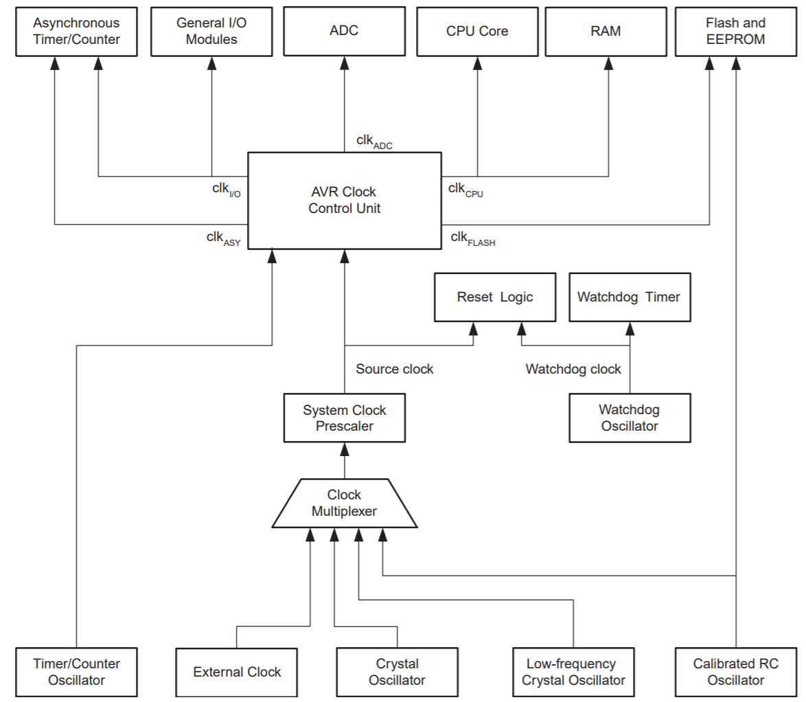
In the datasheet of ATmega1280 the flash and EEPROM unit gets two clock arrows as below: (page 39) enter image description here
and the "safe operating area" is: (page 358) enter image description here
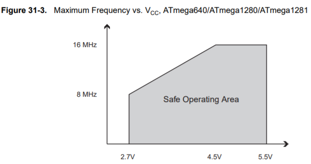
The line is linear between 2.7V and 4.5V, so according to this figure I'm supposed to be above 4.21V to be in the safe zone, but my Vcc is 3.3V and the system works great without any problems. what I'm missing? this graph is for the internal clock? (page 359) enter image description here

How do I need to calculate my safe zone according to my external clock?

LINK to ATmega1280 datasheet

Thanks!

\$\endgroup\$

2 Answers 2

2
\$\begingroup\$

Figure 31-3 is not for the internal clock, the internal clock has nothing to do with this.

Figure 31-3 shows the highest guaranteed operating frequency vs supply voltage.

If you're a designer for a product that will be mass produced which is running this uC run at 14.7 MHz then you better respect this figure and use a supply voltage of at least 4.3 V (4.21 V with some extra margin). That will then guarantee that the uC will work properly.

But my uC works fine at 3.3 V!

Yes and you could be "lucky" that your particular chip is "good" in that respect. But you're using it at room temperature I guess. If you use the uC at a high temperature (for example 80 degrees C) then it will be slower and there is more chance that something fails.

Also not all chips are created equally, there are always some margins in the production process so it is possible that you end up with a "slow" chip. To make designers take that into account figure 31-3 exists so that the designer will use a supply voltage that will guarantee that even the slowest chips will work at for example 14.7 MHz.

So if you're just building a one-off (no mass production) and it works as you want, then that's fine but be aware that you might be "on the edge" and that it might fail (brown out) at high temperatures. If that is no issue: fine. If that is an issue: use a lower clock frequency or increase the supply voltage.

\$\endgroup\$
1
  • \$\begingroup\$ Thanks for the fast answer! \$\endgroup\$ Commented Jun 22, 2020 at 9:24
0
\$\begingroup\$

3.3V supply is not enough for operation at 14.7456 MHz.

It basically reads in a simplified fashion on the first page of datasheet:

ATmega640/ATmega1280/ATmega1281:• 0 - 8MHz @ 2.7V - 5.5V, 0 - 16MHz @ 4.5V - 5.5V

It means that to work at up to 8 MHz you can use down to 2.7V supply, but if you go above 8MHz, you need at least 4.5V supply to work at 16 MHz.

The speed vs voltage curve for ATmega1280 (non-V model) just tells it more detailed way that you need minimum of 4.218V supply for operation at 14.7456 MHz.

ATmega1280V is not even specified to work above 8 MHz.

Sure, some chips may work, but not all, and if something does not work, you don't know what part of the chip fails first, because it may even be a feature or peripheral you are not using at the moment.

So if one of your MCUs work fine, maybe the next one does not work at all, or worse, you spend days debugging a problem with a MCU that only works partially.

\$\endgroup\$
1
  • \$\begingroup\$ Thank you very much! \$\endgroup\$ Commented Jun 22, 2020 at 9:24

Your Answer

By clicking “Post Your Answer”, you agree to our terms of service and acknowledge you have read our privacy policy.

Not the answer you're looking for? Browse other questions tagged or ask your own question.