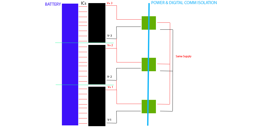
I want to implement a few chips for battery management and due to the ADCs of each cell working at bigger voltages each, and each chip (I have to cascade three ICs LTC6803-4) with a maximum voltage lower than the battery maximum, I have thought if this implementation would work:
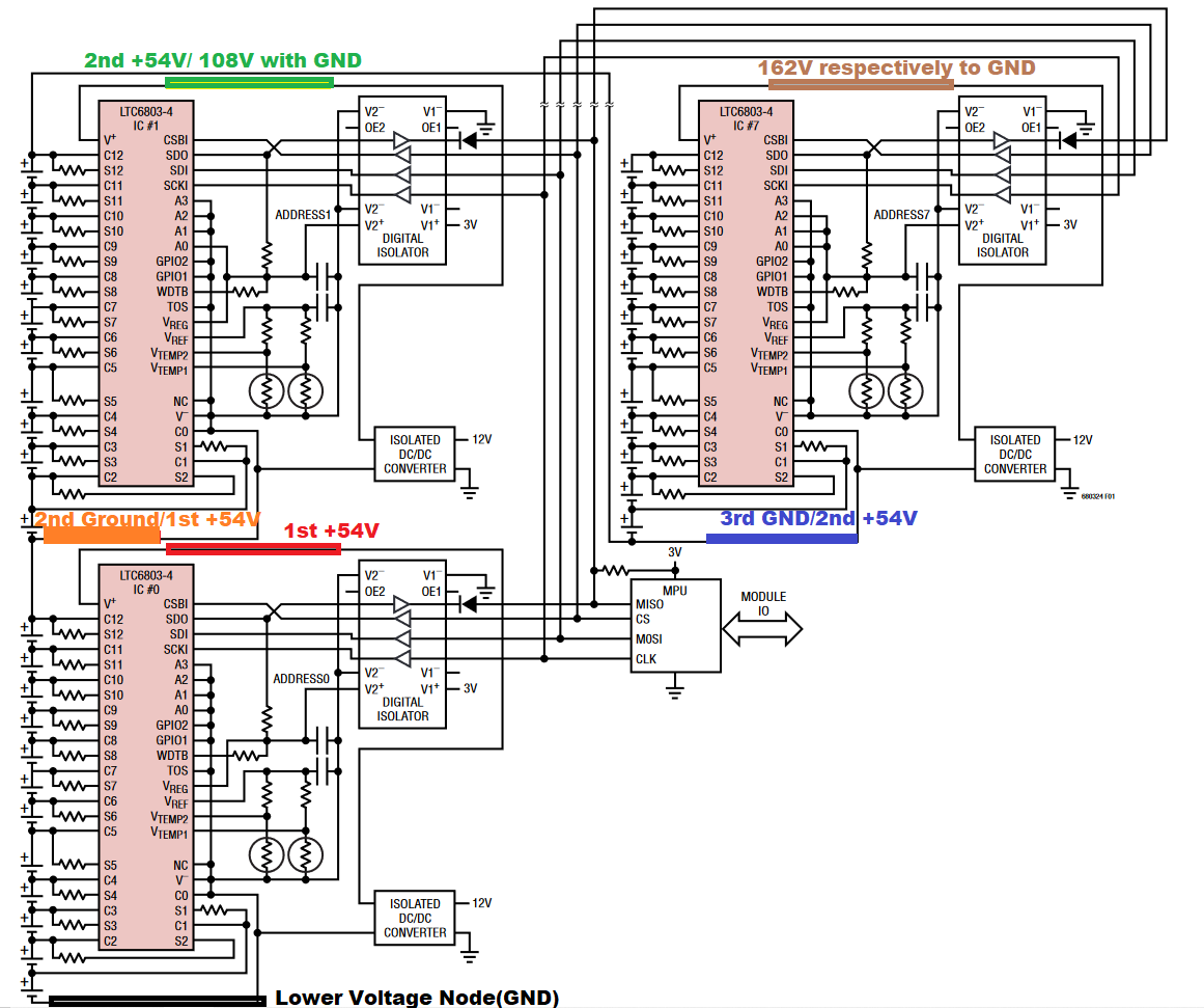
 I have seen something similar in the application example of the datasheet of the IC:

-
1\$\begingroup\$ What is your question? The big takeaway is that you need isolated power supplies and isolated digital interfaces for each stage since each successive stage will be referenced to the first cell in its string. \$\endgroup\$– virCommented Aug 14, 2020 at 19:38
-
1\$\begingroup\$ Use opto logic tranceivers \$\endgroup\$– D.A.S.Commented Aug 14, 2020 at 20:45
-
\$\begingroup\$ @vir the question is if I can connect the V+ 1 to the V- 2 as it will cause that the IC2 is working in top of IC1(speaking in voltage), so I can measure the 2nd pack of 12 cells, because before the isolation, all the power supply is connected at the same GND \$\endgroup\$– Victor CasadoCommented Aug 15, 2020 at 10:02
-
\$\begingroup\$ @TonyStewartSunnyskyguyEE75 ok but at which point? \$\endgroup\$– Victor CasadoCommented Aug 15, 2020 at 10:02
-
\$\begingroup\$ All comm ports that need it due to shift in PS- voltage yet common logic ground need a digital isolator. \$\endgroup\$– D.A.S.Commented Aug 15, 2020 at 10:07
1 Answer
Would that schematic work?
This is basically extrapolating LTC’s 2 stage to 3 , so on the surface , there’s no reason it shouldn’t.
But you have a challenge from me.
Define all the qualitative performance reasons to realize this schematic with improvement options.
Define all the quantitative of your charger system specs that matter with this BMS and tolerances with fault detection and correction mitigation functions needed that need attention.
One of the challenges with cascade BMS is that all batteries must be well matched for capacity and ESR in order the the residual error to be dissipated in heat by the Zener internal diodes.
Also consider including individual thermal sensing, which is critical when 1. occurs unexpectedly and the cells are not thermally coupled. -This is best done with diode Or’ing than thermistors.
- considering the wide tolerances on e-caps & bulk supercaps, LI Ion batteries are no different.
- worse yet, because the weakest cell has the fastest dV/dt they will become the 1st to become under or over charged.
- when undercharged the ESR rises rapidly below 10% SOC resulting in more heat loss with shared current during operation but excess current shunting during CC charging if 1 cell reaches 100% SOC at 4.2V per cell while the string has not reached CV mode.
- since CV mode uses declining currents, the %C deviation determines how long BMS must shunt up,to the power Max. being charged to the other cells.
- this may require you to have more than 1 CC mode so the equalization charge layer can catchup in each cell. I.e. CC to 3.8V x36 cells then Monitor IC temp and reduce CC as required by IC temp. or battery temp to 4.2V x36 then go to into CV mode for a time limited final charge. Or consider 4.1Vx36 or longer life.
Disclaimer: I have not used this excellent solution but has great potential for HV packs.(pun intended)
-
\$\begingroup\$ Thank you for such a detailed response! I am going to implement a passive balancer with a low pass filter in between every Cn/Sn port, not just the resistor shown, so all the batteries will be matched externally to the LTC, and so the heat will be disipated by the external diodes(I attach you the reference design that I am basing my sch: analog.com/media/en/technical-documentation/…) \$\endgroup\$ Commented Aug 15, 2020 at 15:04
-
\$\begingroup\$ I need to manage a 30s4p battery, so my intention is to implement 4 exactly boards, capable of 36 cell monitoring each, so I have option to scale to a bigger battery in the future.I want to build the battery with LiPo cells with a nominal value of 3.7(4.2V peak), so when the max voltage is achieved, the BMS will cut the energy going into the battery, and when the voltage is under lets say 3.4V it will cut the energy going out of the battery. It will also measure temps at different points of the battery to have the heat problem covered too at charging/discharging stages \$\endgroup\$ Commented Aug 15, 2020 at 15:10
-
\$\begingroup\$ Ok but if CC is 5Ah x 4.2V =21W worst case if >10% mismatched after aging, since they all share the same current and you regulated CC on the string until CV on the entire string \$\endgroup\$– D.A.S.Commented Aug 15, 2020 at 15:18
-
\$\begingroup\$ They are 10Ah(with a discharge intensity of 200 A (20 C) Normal, 300 A (30 C) Peak and charge intensity of 20 A (2 C)), so 42W, if I match all the CV by passive balancing, then all of them will feed the same current, don't they? So as much as I balance the voltages between every pair of cells, and have a protection system by under/over voltage, some fuses and current sensors, ans temp sensors at different points, it should be covered, right? \$\endgroup\$ Commented Aug 15, 2020 at 15:35
-
\$\begingroup\$ Nope. All batteries are like supercaps except >10kF and ESR <50mOhm when new so tolerances depend on batch, age use. The smallest C charges the fastest dV/dt=Ic/C except for IESR drop induces a step IESR then the dual layer effect means there are actually 2 or more ESR * C= T time constants, so read my advice carefully \$\endgroup\$– D.A.S.Commented Aug 15, 2020 at 15:39
