3
\$\begingroup\$

(Please note I'm "just" a software developer with some knowledge in EE)

Long story short: We spent an enormous amount of money on 50 boards we have designed for mass programming one of our products. However, we found a problem we did not detect with our tests.

We have a digital isolator (TI ISOW7821DWE, U2) that also features a DC-DC isolator. However, this DC-DC isolator is extremely slow. When applying 5 V to its input, it needs around 5-7 ms to ramp up its output from 0 V to 5 V. With 3.3 V input, it needs almost 9-13 ms from 0 V to 3.3 V output. The LDO supplying the DC-DC isn't the problem, it ramps up its output to 3.3 V or 5 V in <100 µs. This slow ramp-up causes some MCUs on our boards to not start up properly, hence we can not program it.

We tested this with an "known good" DC-DC that ramps up the circuit from 0 V to 5 V in ~100 µs. Using this DC-DC, everything works fine. However, we have the attached circuit and parts now which we need to stick to and therefore somehow patch it.

Is there an easy way to "patch" the circuit, so it only outputs 5 V or 3.3 V to J3 after a certain threshold is reached (like 2 V, 2.8 V, 3.3 V, 3.5 V or 4 V)? I naively tried to use different Z-Diodes as a replacement for L2, with mixed results. The current drawn by our MCU's circuit (which is attached to J3) is around ~2 mA.

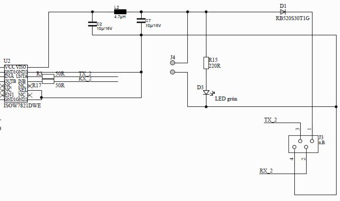
Isolated Circuit

\$\endgroup\$
3
  • \$\begingroup\$ So just to be clear. This schematic is your test jig that you made 50 of? \$\endgroup\$
    – Jeroen3
    Commented Oct 2, 2020 at 6:55
  • \$\begingroup\$ @Jeroen3 its the programmer for our test rig. each programmer features 16 of those isolated circuits for 16 boards. Its currently only for internal testing. However we want to redesign it sometime for mass programming of our devices so we can hand it out to our assembly guys. \$\endgroup\$
    – bam
    Commented Oct 2, 2020 at 6:58
  • \$\begingroup\$ A P-FET and a comparator? \$\endgroup\$
    – winny
    Commented Oct 2, 2020 at 7:13

2 Answers 2

5
\$\begingroup\$
  1. You could try to reduce the capacitance C2 and C7.
    I suspect just for programming the noise on the supply voltage isn't that critical.

  2. Remove the isolation.
    Do you really need the isolator to program your boards? Can you do without? Can you put the isolation barrier somewhere else, like the USB plug?
    Or only bypass the power part.

  3. Bodge a chip on it. Like the NCP361 Protection Controller.


The correct way is to use a voltage monitor. However I suspect your actual product requires this if it's this susceptible to supply problems. Not the test jig.

\$\endgroup\$
1
  • 1
    \$\begingroup\$ I just found the ROHM BU4928 which enables Vout at 2.8V and ramps up in just µseconds. They are cheap, can supply 70mA on Vout and come in an SOT23 footprint. Perfect! \$\endgroup\$
    – bam
    Commented Oct 2, 2020 at 7:46
2
\$\begingroup\$

Maybe hack a p-channel MOSFET in series with the choke and add a TO-92 voltage detector with push-pull output to drive the MOSFET.

A good technician should be able to reliably hack those two parts in there.

\$\endgroup\$

Your Answer

By clicking “Post Your Answer”, you agree to our terms of service and acknowledge you have read our privacy policy.

Not the answer you're looking for? Browse other questions tagged or ask your own question.