1
\$\begingroup\$

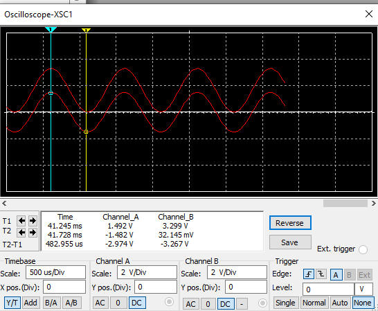
I'm building an op-amp circuit that takes my electric guitar signal shifts the voltage from -1.5V to 1.5V to a 0-3V. I have this circuit that works perfectly with a dual supply op amp in multisim, but when I use the single supply op-amp the output gets cut off at about 1.7V, halfway lower than I want it. I tried this with MCP2006 I/P(single supply) and the TL972 IP(dual supply). I used identical circuits (besides the power supplies of course) on both in multisim. My circuit will be battery powered so making a negative supply shouldn't be too difficult I'd just rather use one battery. Also, I'm just kinda curious as to why it doesn't work that way. OP-Amp
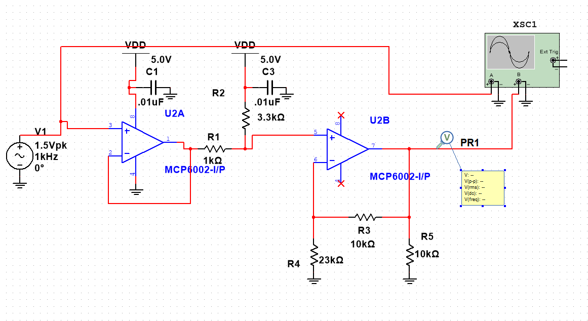
Here are the different oscilloscope readings MCP2006 I/P and TL972 IP, respectively. MCP2006 I/P
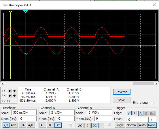
TL972 IP

\$\endgroup\$
2
  • \$\begingroup\$ Opamp's output can't swing above the positive supply and below the negative supply. That's why you get the clipping. So you need a DC bias. Note: Any opamp can operate with single supply. By the way, shouldn't it be MCP6002, not 2006? \$\endgroup\$ Commented Oct 30, 2020 at 3:31
  • \$\begingroup\$ You're applying a negative input voltage to your single supply opamp during half of the cycle, so you're seeing the output flat-line because it can't go negative. You should DC bias the input to half-supply and AC couple the input signal. \$\endgroup\$
    – brhans
    Commented Oct 30, 2020 at 4:20

1 Answer 1

1
\$\begingroup\$

enter image description here

Figure 1. Internals of the ancient 741 opamp. Source: Wikipedia.

From the internal schematic of the 741 op-amp it should be clear that the output can source current from the \$ V_{S+} \$ rail via Q14 or sink current to the \$ V_{S-} \$ rail via Q20.

It is not possible to generate an output voltage higher than the postive supply pin or more negative than the negative supply pin. This means that when the input to your first stage voltage follower goes negative the op-amp can't follow it and it clips at zero volts. To fix this you need to either:

  1. Use a dual supply.
  2. Use a decoupling capacitor on the input and bias the input to op-amp 1 to half-supply. This is the technique used on most 9 V guitar effects pedals.

It appears that you might be trying to apply a bias with R1 and R2 but it's too late. If you fix the input problem you can remove them.

R5 is redundant and may be removed.

If you fix the input to bias it to half-supply there will be a DC bias on the output so you'll need a decoupling (DC-blocking) capacitor there too.

\$\endgroup\$
2
  • \$\begingroup\$ I moved the DC bias resistors before the buffer op amp and it works perfectly now. What is the point of the decoupling capacitor? \$\endgroup\$
    – Jacob Lara
    Commented Oct 30, 2020 at 21:36
  • \$\begingroup\$ You don't want to drive a DC current from your preamp's input back out through your guitar pickup and you don't want DC going into whatever this circuit is feeding into. \$\endgroup\$
    – Transistor
    Commented Oct 30, 2020 at 21:47

Your Answer

By clicking “Post Your Answer”, you agree to our terms of service and acknowledge you have read our privacy policy.

Not the answer you're looking for? Browse other questions tagged or ask your own question.