4
\$\begingroup\$

I'm attempting to fix an SMPS for a sewing machine that is having all of its outputs voltages a third from what's expected.

I've replaced all electrolytic capacitors and nothing seems to be producing heat that would indicate a short circuit, so I'm thinking it might be its feedback loop. This board utilizes the module MR4030 to control the Energy transferred from primary to the secondary but I didn't see any TL431 and I suspect it's the 4A 0F3 that I don't know about but I couldn't find what it is to consider to replace it.

4A 0F3

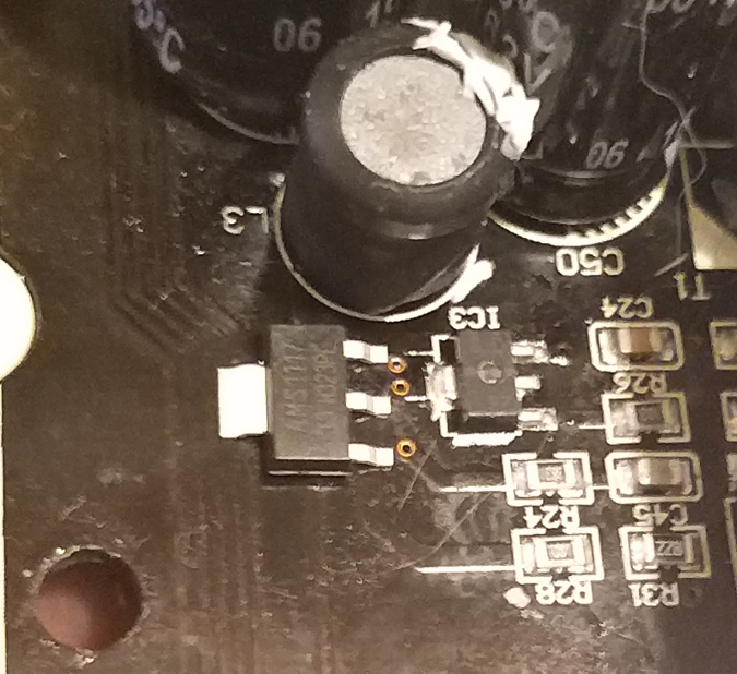
There's another component as well that I don't recognize shown below. Do you recognize it?

Unknown component

Full board (the model of this board is HSV-MC122072):

Full Board

Looking at the image of the whole circuit below the two big blue capacitors on the "small" heat sink is the bridge diode and down under it is the circuit that controls the motor of the sewing machine, which it does through a relay and other stuff. On the left of the two big blue capacitors with the bigger heat sink is the MR4030 which has the Mosfet that does the switching, then more on the left is the transformer to the Secondary part of the circuit. Right under the MR4030 has an Optocoupler and a bit more down to the left is the component in question what I think it's the shunt regulator.

And here is a look underneath.

underneath the board

Picture comparison of the unknown component with a SOT-223 package. enter image description here
\$\endgroup\$
14
  • 3
    \$\begingroup\$ TL431 is not a power device so I don't think it is available in SOT-223, I've only seen SOT-23 in SMD, this is probably something diffirent. The module on the bottom picture is a triple IGBT bridge for motor drive. Here's a datasheet for a similar (but diffirent!) part: onsemi.com/pub/Collateral/FSBB30CH60C-D.pdf \$\endgroup\$ Commented Oct 31, 2020 at 8:21
  • 1
    \$\begingroup\$ A couple more pictures of the full SMPS circuit may help with analysis. Also spend a some more time looking for videos and blogs where someone may have repaired the same unit, use PCB and component part numbers, and foreign country machine numbers as well if you can because sometimes a Russian dude has done repairs on the same unit with a different model number and has traced the schematic for you. \$\endgroup\$
    – KalleMP
    Commented Oct 31, 2020 at 9:45
  • 1
    \$\begingroup\$ @RinaldiSegecin Given the new picture it looks like it might be a SOT-89. Small signal PNP STF2907A from ST micro has marking 03F, according to the ST datasheet. You can try your multimeter on diode test to see if it checks out as a PNP BJT. TL431 is also available in SOT-89, but I cannot find any manufacturer with those markings. \$\endgroup\$ Commented Nov 1, 2020 at 5:17
  • 2
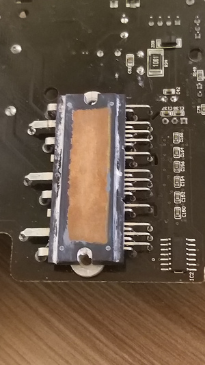
    \$\begingroup\$ The second unknown component, I would guess is some kind of IGBT power module. Perhaps used as a motor driver for the sewing machine? \$\endgroup\$
    – Hearth
    Commented Jul 28, 2021 at 13:21
  • 1
    \$\begingroup\$ Just looking at the PCB thermal damage it's obvious the 3 phase bridge has been toasted. \$\endgroup\$
    – D.A.S.
    Commented Aug 30, 2021 at 21:01

3 Answers 3

2
\$\begingroup\$

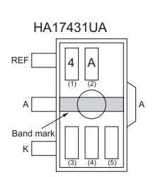
It is a HA17431UA shunt regulator chip. Similar to a TL431, Vref = 2.50V.

enter image description here

The large chip is probably a motor driver array of some kind. The pins suggest it is for driving a sizable 3-phase BLDC motor.

\$\endgroup\$
2
  • \$\begingroup\$ Thank you very much Spehro, I think it might just be it. I'll see if I can get the board back to fix it =) \$\endgroup\$ Commented Aug 31, 2021 at 20:11
  • 1
    \$\begingroup\$ @RinaldiSegecin I doubt that this part is the issue. Alexsey below seems to have some detailed troubleshooting info (he even had a partial on this part number). I would expect a mechanical issue or a stressed part such as a high voltage transistor to be the root cause. \$\endgroup\$ Commented Sep 1, 2021 at 2:06
2
\$\begingroup\$

Please check the switching circuit on power board as below:

  • TR2 (MR403), R22 (150mΩ, C21 (471/1 kV), ZD1 (DL4746), ZD2 (1.5ke/400A), R19 & 20 (51kΩ/2512), C19 (47uF/50V), C23(2200uF/25V), D2 (EA61FC4), D16 (UF4007), IC3 (HA17431), OI4 (HCPL-181), OI10 (HCPL-181)..ETC..,

  • If TR2 burnt, please check the TR2 around whether the disconnection. TR2#7 ~ P+(310V), TR2#5 ~ D6, TR2#4 ~ZD1, TR2#3 ~ GND.

  • Please check the important voltage on circuit. For example; P+, VD, 12V, 5V.

  • Please check coil L1, L2 on EMI board for pin broken.

  • Please check the fuses F1 and F3 (15A/250V) on EMI board for burnt.

  • Please check the resistor R18-2.4k/2512 for MR-4030 switching system. The modified one is R18-470Ω/2512.

\$\endgroup\$
-1
\$\begingroup\$

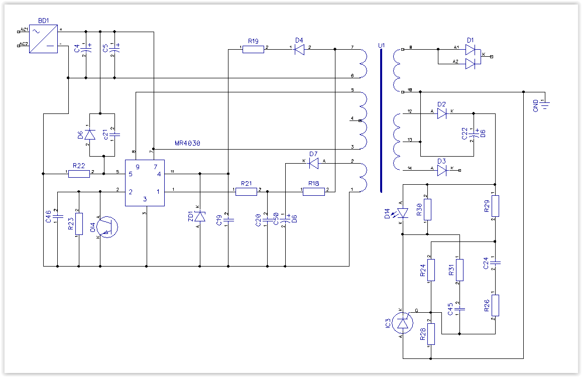
If it is still relevant, then I wick the diagram of a typical inclusion of the MR4030 and a diagram drawn from the board (tester and oscilloscope)

. enter image description here

\$\endgroup\$
1
  • 3
    \$\begingroup\$ Please use English. \$\endgroup\$
    – Null
    Commented Nov 15, 2021 at 13:42

Your Answer

By clicking “Post Your Answer”, you agree to our terms of service and acknowledge you have read our privacy policy.

Not the answer you're looking for? Browse other questions tagged or ask your own question.