1
\$\begingroup\$

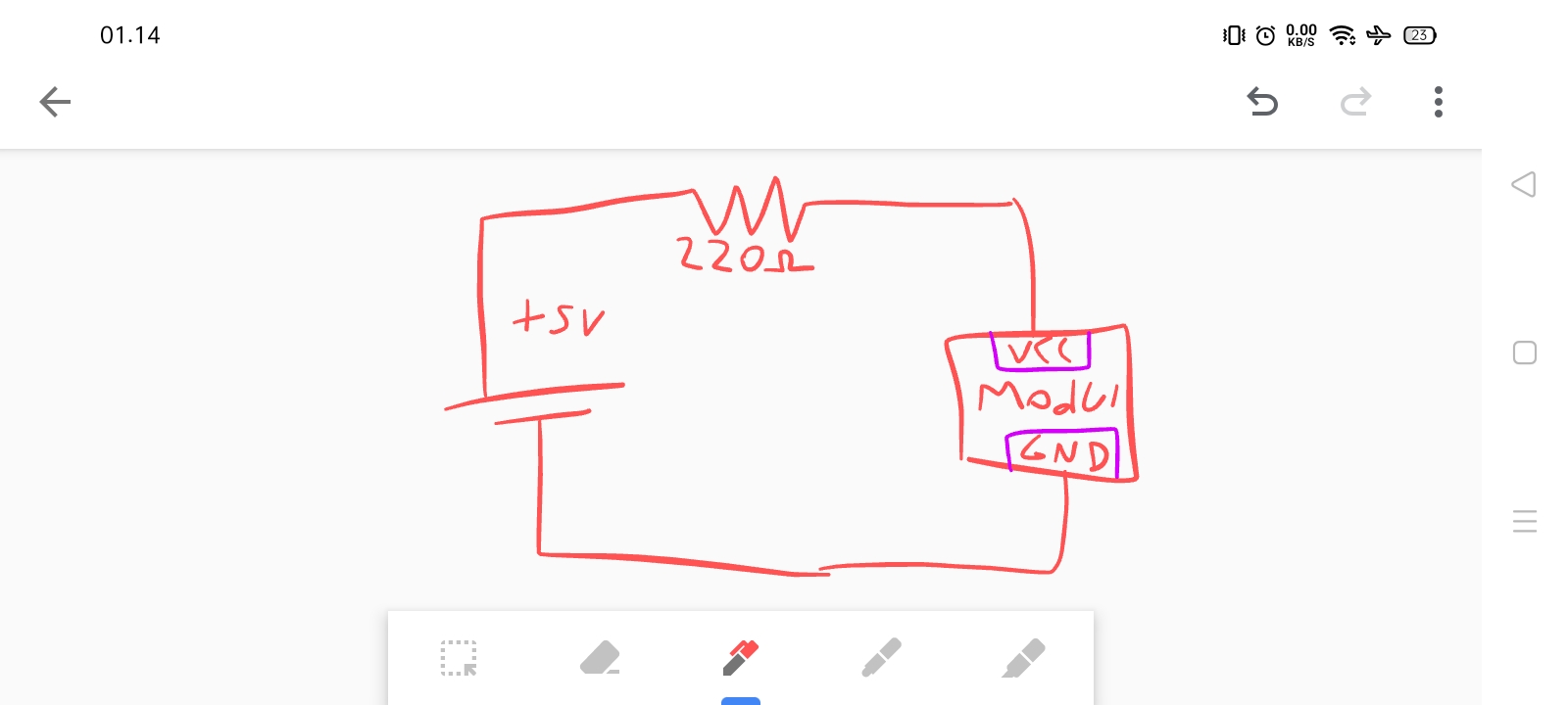
A SIM800L module needs voltage between 3.7V to 4.2V. The Arduino power source output is 5 volts which will damage the module.

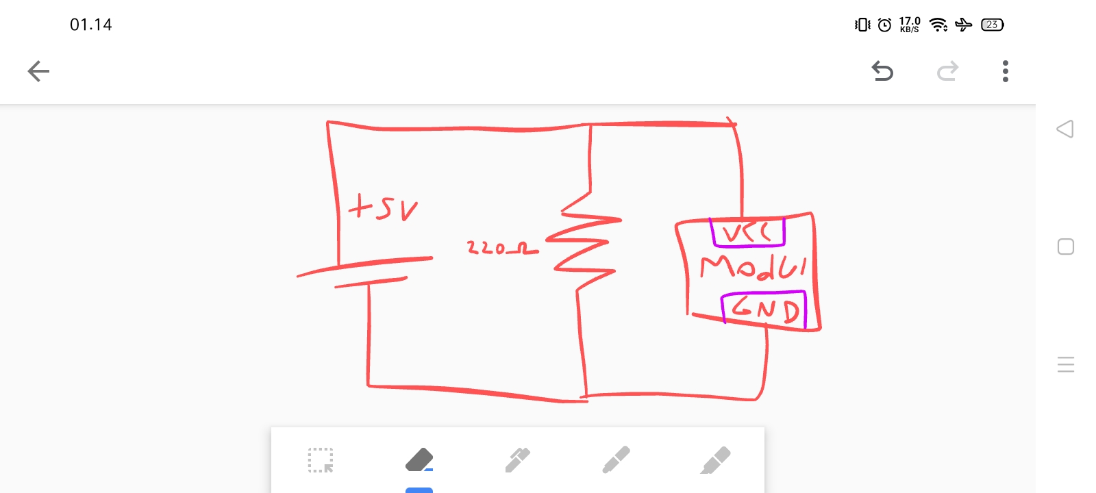
Is 220ohm enough? I was testing with a multimeter. Its drops to 4 volt with parallel circuit like this:

paralel

What is different with a series circuit? Which is better? Series or parallel to drop the voltage?

enter image description here

\$\endgroup\$
4
  • 2
    \$\begingroup\$ You cannot create a power supply (especially not for something with 2 amp pulse loads!) using a voltage divider. You will need a high current regulator. However, you will also need level translation. Please do some research to see suitable setups for this module - eg, Adafruit's FONA, etc. Note that many use the battery the module is designed to run on, rather than trying to create a power source for it, as it's not trivial at all. Also beware that module is obsolete and only supports mobile network standards which are being phased out. \$\endgroup\$ Commented Dec 11, 2020 at 18:26
  • 3
    \$\begingroup\$ Voting to close as we already have a question on this at How to properly power sim800l module? beware however that as mentioned above it is not just an issue of power but also communication, and many naive designs cannot support the pulse current needs. \$\endgroup\$ Commented Dec 11, 2020 at 18:28
  • \$\begingroup\$ I still want ask about this on that old thread but it said i need 50reputation to ask. \$\endgroup\$ Commented Dec 12, 2020 at 0:37
  • \$\begingroup\$ Can PWM output on microcontroller (arduino) act like a VCC power source? So i can control the voltage i want. \$\endgroup\$ Commented Dec 12, 2020 at 0:38

3 Answers 3

4
\$\begingroup\$

The module requires 4.0V nominal (recommended) with up to 2A peak consumption and as low as a few mA when idle.

Forget about using a voltage divider. You would need to burn hundreds of watts in the divider to get reasonable regulation over that range.

You need a voltage regulator. A switchmode module based a chip such as the XL4016 would work, however the SMPS noise might interfere with the radio. The LM2596 modules are a bit marginal in terms of dropout voltage.

A linear LDO regulator capable of handling 2A peak with less than 1.2V dropout is possible, but they tend to be a bit expensive.

As well as the supply voltage you need to ensure inputs are kept within the safe range. You can use a voltage divider to reduce the TX output of the AVR to a safe voltage.

\$\endgroup\$
2
  • 1
    \$\begingroup\$ You might consider adding this solid response at electronics.stackexchange.com/questions/306730/… so that we can close this one as a duplicate and have one question on doing it right (or there might be a better nominee, but that's the first clearly stated one I found) \$\endgroup\$ Commented Dec 11, 2020 at 19:13
  • \$\begingroup\$ @ChrisStratton Done \$\endgroup\$ Commented Dec 11, 2020 at 19:26
2
\$\begingroup\$

You could use a simple series resistor, but to compute the right resistor you'll need to know how much current your load draws. R = E/I. In this case, the E we care about is the voltage drop we want (1 volt). Plug in the current the load will draw, and compute the resistance you need. There are serious problems here though. First of all, the voltage seen by your load will vary depending on how much current it draws, so unless its current draw is nearly constant, this approach simply can't work at all. Second, all the current flowing into the load also flows through the resistor, so unless its current draw is extremely low, your resistor is going to be dissipating a lot of energy.

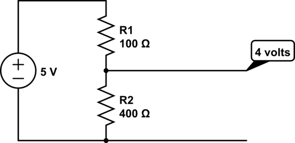
To make it work regardless of the current drawn by the load, you could (at least theoretically) use a voltage divider:
schematic

simulate this circuit – Schematic created using CircuitLab

Even with a voltage divider, however, you want to design it for approximately the current your load will draw. The ratio of the resistors determines the output voltage, but all the current going to the load has to flow through the upper resistor, so with the values I used here, you have 5 volts through 100 ohms, giving a maximum of 5/100 = 50 ma.

Reducing the resistor values will increase the maximum current you can draw. So if we used 1 ohm and 4 ohms, the load could draw up to 5 amps.

But if we do that, it means that even when the load isn't drawing anything, the source is seeing a load of only 5 ohms, so it'll try to draw 1 amp. Again, our resistors are dissipating a lot of energy, which means you'll need big, expensive power resistors, and you're simply wasting a ridiculous amount of energy.

So, a voltage divider can maintain a (reasonably) constant voltage across changes in current draw, but you still want to choose the largest resistance values you can that will still supply the current you need. This will minimize the current you're constantly drawing from the source.

A voltage divider can work reasonably well as long as you only need really low current or if you only need to reduce the voltage by a tiny margin. But if you need to reduce voltage much and/or draw much current, you'll end up with a lot of energy being burned in the resistors themselves. It's particularly bad if your load's current draw varies widely, so you need to use low-value resistors to support the necessary current, so you're wasting a lot of energy all the time just to support a large current draw once in a while.

Unless your current requirements are extremely low, you usually want a buck converter, not resistors.

\$\endgroup\$
2
\$\begingroup\$

There is no way you can power the SIM800 module with resistors from Arduino.

\$\endgroup\$
5
  • 1
    \$\begingroup\$ No sane way at least. If you used really low value power resistors such that something like 10 amps were passing through the divider before the module drew anything, it might work. But no, don't do that. \$\endgroup\$ Commented Dec 11, 2020 at 18:30
  • \$\begingroup\$ Jerry it is the same thing. \$\endgroup\$ Commented Dec 11, 2020 at 19:01
  • \$\begingroup\$ @TheForceAwakens: no, it most certainly is not. One of them is a flat-out lie (unless the person who made the statement just doesn't have a clue of what they're talking about--but it's absolutely false in any case). \$\endgroup\$ Commented Dec 11, 2020 at 19:22
  • \$\begingroup\$ @JerryCoffin Flat out lie? The SIM800 module requires voltage between 3.4 and 4.4V to operate, and it can consume 0.7mA in sleep mode and 2000mA in transmit mode. To provide such a voltage and current range from 5V supply, you need to waste 1056mA (5280mW) in the resistive divider to make 4.4V, and when module draws 2A, the resistor network requires 2816mA as input to make 2A of 3.4V. Now, can the Arduino provide the required 2.8A out? The 5V regulator after DC jack is not rated for that. Neither are components from the USB connector to make 5V. So please show how it could work? \$\endgroup\$
    – Justme
    Commented Dec 11, 2020 at 20:33
  • \$\begingroup\$ @JerryCoffin All it says to use Arduino as power source, so the assumption is that whatever powers the Arduino, the 5V output on Arduino would be used to power the SIM800 module. And I will have to assume that since the OP has says SIM800 module needs 3.4V and how to make 3.4V with resistors that this is about powering the SIM800 module with resistors. And SIM800 datasheet does list current consumption. I think the question is not how to make 3.4V with no current ability at all like using megaohm grade resistors. \$\endgroup\$
    – Justme
    Commented Dec 11, 2020 at 20:48

Not the answer you're looking for? Browse other questions tagged or ask your own question.