8
\$\begingroup\$

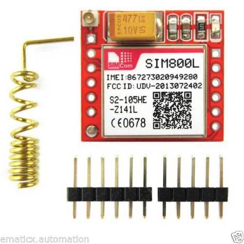
I have this sim800L module enter image description here

It has a 3.7v - 4.2v voltage requirement. So I created a simple buck regulator using MIC4576 regulator according to it's schematics and adjusted it's output to 4.2 volts. It can provide 3A of current. And i powered it through my laptop charger, so there's no shortage of current in the circuit.

But the module(sim800l) resets as soon as it finds a network(it's my guess). If I run it without sim, it runs fine and doesn't reset.

I've also tried 2 18650s in parallel to be able to provide atleast 3A to the circuit. But it still resets after a few seconds.

Is there anything obvious I'm missing?

\$\endgroup\$
13
  • 1
    \$\begingroup\$ @SamGibson I don't have an oscilloscope :( But I've measured the voltage when it's powered and I've noticed that voltage drops from 4.2v to about 3.8v for a brief time when it restarts. I don't know why this happens since I'm supplying 3 amps of current. \$\endgroup\$ Commented May 25, 2017 at 8:51
  • 1
    \$\begingroup\$ @suraj Could you look into section 4.1.1(Power Supply Pin) in the SIM800 PDF for Hardware design and confirm all the things stated are alright in your case. I feel that is where the issue lies. One spike below the 3 V can trigger a reset . \$\endgroup\$
    – MaNyYaCk
    Commented May 25, 2017 at 11:48
  • 1
    \$\begingroup\$ @MaNyYaCk Yes you are right. but the problem is, the voltage doesn't go below 3v it goes to about 3.8v. \$\endgroup\$ Commented May 25, 2017 at 16:38
  • 1
    \$\begingroup\$ @SurajBhawal Did you found that out on Oscilloscope or DMM? Some multimeters aren't accurate to show a sudden spike \$\endgroup\$
    – MaNyYaCk
    Commented May 25, 2017 at 16:54
  • 3
    \$\begingroup\$ You may be able to use the ADC of a microcontroller board or Arduino to measure voltage as a function of time, especially if you devise something that measures rapidly and reports the lowest value seen. It won't have the bandwidth of a true scope, but if you have reasonable capacitance in the power supply it may be good enough to get a sense of what is happening. \$\endgroup\$ Commented May 25, 2017 at 17:54

4 Answers 4

5
\$\begingroup\$

Everything you are reporting is consistent with insufficient power to the GSM module, when it tries to register with the network, even though you think your power supply is OK.

Do you have access to an oscilloscope and experience using it?

I don't have an oscilloscope :(

The lack of an oscilloscope means that, using a multimeter instead, you cannot know the true voltage for any short dips (or spikes) due to the low sampling rate of multimeters. (Oscilloscopes have limitations too, but with their much higher sampling rates then for issues like this, an oscilloscope is usually sufficiently fast to show the necessary detail.)

But I've measured the voltage when it's powered and I've noticed that voltage drops from 4.2v to about 3.8v for a brief time when it restarts.

That result tells you that you do need to investigate the power delivery to the GSM module further, as the voltage at the module could actually dip lower than the 3.8 V reading you have reported, for the reason that I explained above.

I created a simple buck regulator using MIC4576 regulator according to it's schematics and adjusted it's output to 4.2 volts. It can provide 3A of current.

Not necessarily true. Depending on exact construction method, component layout, and component choices, I could make a buck regulator which will not provide the maximum current which the switching device itself (in your case, the MIC4576) is capable of. Or to say it another way: You need to prove that the power supply is really capable of supplying that voltage to the GSM module - you cannot assume that a 3A switcher, in a home-built design, is actually capable of supplying its full "off load" voltage, at the rated current.

The thickness and length of the wiring between the power supply and the GSM module, also affect inductance and resistance and so affect the power available at the GSM module.

i powered it through my laptop charger, so there's no shortage of current in the circuit.

Again, you cannot assume that. I have seen laptop power supplies which did not meet their claimed specifications (especially third-party ones from ebay etc.).

Some choices for you include:

  • Use a friend's or colleague's known-working GSM module + power supply setup, and substitute just your GSM module (i.e. use their known-good power supply).
  • Try using shorter and/or using thicker wires between the power supply and GSM module, to reduce the voltage drop there.
  • Get access to an oscilloscope to perform further measurements.
  • In some cases (especially with marginal power supplies, long power cables etc.) adding extra capacitance on the GSM module, can help during the high-power GSM transmission bursts. A remote possibility is that you have a defective GSM module e.g. that large tantalum capacitor on the "stock photo" you gave, might be faulty.
\$\endgroup\$
1
  • 1
    \$\begingroup\$ Thanks for such detailed explanation.. I've tested the current capability of my reg. circuit using a dummy load and a multimeter and it's supplying well over 2A. also my laptop charger is a genuine one with rated 4.5A capability. I also tried with thicker wires and adding a capacitor bank at module side without success. I don't have access to an oscilloscope anywhere, but I'll try the method suggested Chris. \$\endgroup\$ Commented May 26, 2017 at 15:37
4
\$\begingroup\$

General considerations regarding powering and interfacing the module, not related to OP's issues most likely.

The module requires 4.0V nominal (recommended) with up to 2A peak consumption and as low as a few mA when idle.

Forget about using a voltage divider. You would need to burn hundreds of watts in the divider to get reasonable regulation over that range.

You need a voltage regulator. A switchmode module based a chip such as the XL4016 would work, however the SMPS noise might interfere with the radio. The LM2596 modules are a bit marginal in terms of dropout voltage.

A linear LDO regulator capable of handling 2A peak with less than 1.2V dropout is possible, but they tend to be a bit expensive.

As well as the supply voltage you need to ensure inputs are kept within the safe range. You can use a voltage divider to reduce the TX output of the AVR to a safe voltage.

Source :How to drop voltage to 4 volt from 5 volt source voltage with resistors?

\$\endgroup\$
7
  • \$\begingroup\$ Spehro - Hi, Of course these are all good suggestions from the linked question. However in this question (a) no-one suggested using a voltage divider or LDO, and (b) the OP was already using a buck regulator. The issue here was that, despite doing that, their SIM800L module still behaved as if it was suffering from voltage droop. || So those suggestions you've kindly given, while good in general, rather "miss the point" for this specific question and which I tried to help with, at the time. Unfortunately the OP didn't come back with an update about what solved their problem (if anything). \$\endgroup\$
    – SamGibson
    Commented Dec 11, 2020 at 20:01
  • \$\begingroup\$ @SamGibson Good point, and the idea was to try to amalgamate similar answers on care and feeding of this module. \$\endgroup\$ Commented Dec 11, 2020 at 20:03
  • \$\begingroup\$ Spehro - "the idea was to try to amalgamate similar answers on care and feeding of this module" Understood. However by normal criteria, IMHO your answer (which I know comes from elsewhere where it does answer that question) does not answer this specific situation. If we're going to amalgamate all "how to power SIM800L" questions, then this is not the one to choose as the question to add all the answers onto, as so many of the answers elsewhere won't be applicable here! Or else we somehow need to highlight to readers that some answers here won't apply to the original question?!?! Messy \$\endgroup\$
    – SamGibson
    Commented Dec 11, 2020 at 20:13
  • 1
    \$\begingroup\$ Speaking honestly - I think choosing this question to receive "more general answers" was premature, as it is not the typical type of "GPS module doesn't work properly when SIM is inserted" question that I have seen over the years, where even the basics weren't correct. Even Chris who linked to this one, said "there might be a better nominee, but that's the first clearly stated one I found", but now you've added an answer, it's out of my hands so I'll stop here. I can only control what I do & say what I believe is best for future readers. Others have different opinions :-) Sincere regards. \$\endgroup\$
    – SamGibson
    Commented Dec 11, 2020 at 20:24
  • 1
    \$\begingroup\$ @SamGibson Well, I've upvoted your good work anyway. \$\endgroup\$ Commented Dec 11, 2020 at 20:25
1
\$\begingroup\$

I was using a reasonable 2.5A bench power supply to feed my module, and sending AT to the module received OK back as expected.

However, sending commmands which required network access (ie transmission from the module) often resulted in a reply from the module of ERROR.

I added a 1uF and a 22uF electrolytic close to the module and it now works reliably. Then I checked the datasheet, it recommends 10uF, 33pF and 10pF close to the module (these may be on the PCB in the stock image) to supply the peaks of current required during transmission.

A high current bench supply may not be able to change its output current rapidly enough to supply the bursts of current required, resulting in erroneous transmissions.

\$\endgroup\$
0
\$\begingroup\$

OP is a typical case of the module not getting enough juice.

Sorry for the non-technical answer, this answer is only through my experience.

If you want to get it running for sure, feed the module with a cheap DC-DC buck converter, those regulable with the trim pot using a LM2596S. They have a 220uF 35V capacitor at the output. Regulate it to approx. 4v and add another capacitor to the output. I'm using a 3300uF 6.3V. It's kind of big but they are cheap anyway.

\$\endgroup\$

Your Answer

By clicking “Post Your Answer”, you agree to our terms of service and acknowledge you have read our privacy policy.

Not the answer you're looking for? Browse other questions tagged or ask your own question.