3
\$\begingroup\$

We have a small IoT device, that runs of an external 24v DC power supply brick (https://www.rapidonline.com/tt-electronics-t6367st-24vdc-60w-installation-smpsu-85-3795)

This 24v supply connects to the input side of a switch-mode converter (TPS56637) through a power barrel (L722RAS), that converts it to 3.4v used internally in the device. The switch-mode supply is designed by TI's Webench Power Designer (https://webench.ti.com/power-designer/switching-regulator?powerSupply=0). The specific design report is available here: https://www.dropbox.com/s/2uqugyhv0k8v8zb/Power%20supply%20report%20-%203v5.pdf?dl=0

The problem is, that we sometimes experience that plugging in the power connector kills the switch-mode controller. We cannot seem to figure out why this happens, though we suspect high in-rush currents from the output capacitors in the AC-DC brick? What is the appropriate way of solving an issue like this? We can replicate the problem by inserting and removing the power connecter a few times within a short timeframe.

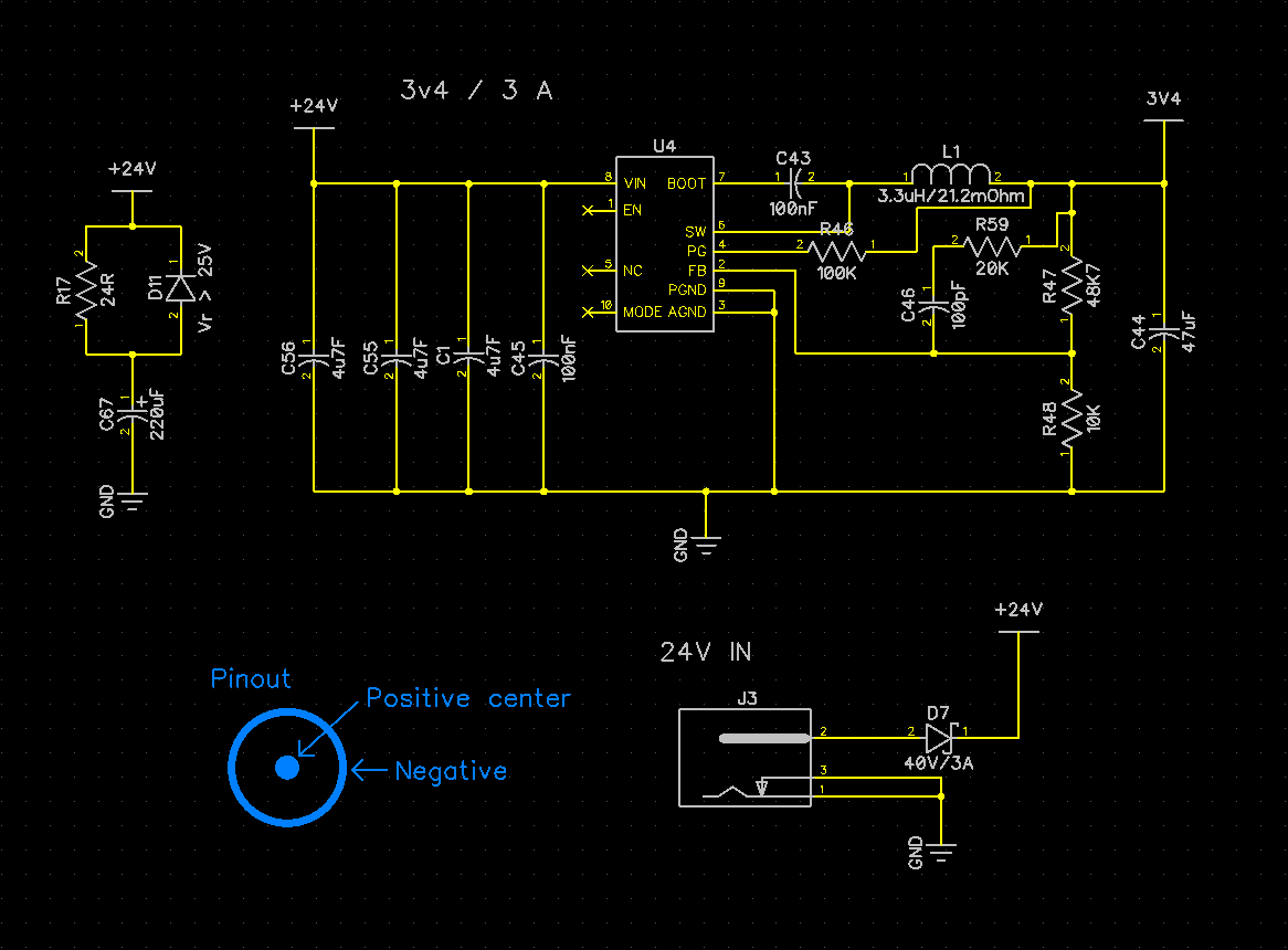
Relevant parts of the schematic: Schematics

\$\endgroup\$
4
  • \$\begingroup\$ How big is the load? \$\endgroup\$
    – K H
    Commented Jan 28, 2021 at 7:49
  • \$\begingroup\$ Not very big in the beginning, but the device contains a cellular modem and wifi, so it draws a bit more from time-to-time. Avg load is less than 0.5A @ 3v \$\endgroup\$
    – smilykoch
    Commented Jan 28, 2021 at 7:56
  • \$\begingroup\$ Did you measure the output of the L722RAS before plugging it into your converter? If its output is high when unloaded (e.g. 28V) then can kill the converter when plugged in. \$\endgroup\$ Commented Jan 28, 2021 at 9:08
  • \$\begingroup\$ There are several things you can du blindly but first order of business should be to capture the problem and understand it. It will probably not be easy. Can you make a jig that cycle your powersupply until destruction while logging? \$\endgroup\$
    – winny
    Commented Jan 28, 2021 at 9:13

1 Answer 1

4
\$\begingroup\$

Your cables are inductive, and you will have an inrush to charge your capacitors. When the inrush stops the inductive cables will generate a voltage overshoot.

LT has an excellent application note on the issue.

https://www.analog.com/media/en/technical-documentation/application-notes/an88f.pdf

However; The application note highlights high-esr capacitors as a solution. I disagree with that, as ESR is a parameter that changes during the lifetime of the capacitor. I recommend using a TVS diode.

\$\endgroup\$
4
  • \$\begingroup\$ Aha, so a 24v TVS placed like this might solve our problem? analogictips.com/faq-transient-voltage-suppression-diode . Also the C67, R17, D11 combination, is that the correct way of putting those? The C67 is an aluminium cap. Would it make sense to remove D7, and use the TVS as reverse polarity protection as well? \$\endgroup\$
    – smilykoch
    Commented Jan 28, 2021 at 9:23
  • \$\begingroup\$ Yea, that will most certainly help. Using large TVS as reverse protection, in combination with a fuse or PTC, is being done but I am not a huge fan. Placing a bi-directional TVS at the front of your reverse-blocking diode, near the connector, will also prevent transient effects to destroy your blocking diode, and you can consider to use a low-Vf Schottky there. Not quite sure about your C67, R17, D11 contraptioon. it all depends on the rating on D11. Your converter doesn't have a huge amount of headroom, so D11 is probably not clamping sufficiently. This can be measured with an oscilloscope. \$\endgroup\$
    – Arcatus
    Commented Jan 28, 2021 at 9:54
  • \$\begingroup\$ We have now tried with a TVS directly at the input, but even with a 26v TVS, we still see voltage overshoot spikes of 30-32v, still enough to kill our power converter. Any suggestions for improvements beyond just the TVS? \$\endgroup\$
    – smilykoch
    Commented Feb 2, 2021 at 18:44
  • \$\begingroup\$ It has been a while but did you solve this? I found this post the hard way today, after letting the magic smoke out of an SMPS circuit I built from a WEBENCH design. The absolute max for my part is 26V, I am hoping to run it at 24V. \$\endgroup\$
    – David
    Commented Sep 16, 2023 at 20:17

Your Answer

By clicking “Post Your Answer”, you agree to our terms of service and acknowledge you have read our privacy policy.

Not the answer you're looking for? Browse other questions tagged or ask your own question.