1
\$\begingroup\$

I am studying boost converters in my power electronics class. Something I cannot wrap my head around is the voltage across the inductor.

When the low side switch (the switch connected to ground, see diagram below) is closed, the circuit is just an inductor in series with a DC voltage source. According to every reference I can find on the internet and an LTspice simulation I downloaded from my professor, the voltage across the inductor is just Vi and stays at Vi for the time that the low side switch is closed. This makes sense according to KVL - the voltage around the loop has to equal 0 one way or another.

However, wouldn't the voltage be changing? If we just take the simple circuit of a DC voltage supply in series with an inductor, eventually after some time, the voltage across the inductor would just equal 0 and the source would be shorted to ground, right? So why is it different in a boost converter? What makes the voltage across the inductor stay constant at Vi?

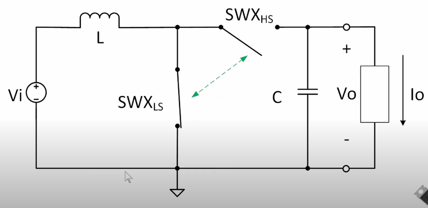
enter image description here

\$\endgroup\$

2 Answers 2

3
\$\begingroup\$

What makes the voltage across the inductor stay constant at Vi?
It stays constant because the incoming supply defines that voltage but, if you left the inductor connected across the supply, after a few tens of microseconds, the current might be tens or hundreds of amps and that will cause the incoming supply to collapse. Then you're in trouble.

But that isn't how a boost circuit works. The inductor is placed in parallel with the supply and current ramps up to "several" amps. That peak current is, in effect, representing the stored energy in the inductor. Microseconds later, the inductor is disconnected from the incoming supply and, that stored energy is released into the output capacitor and load. Then the process starts again.

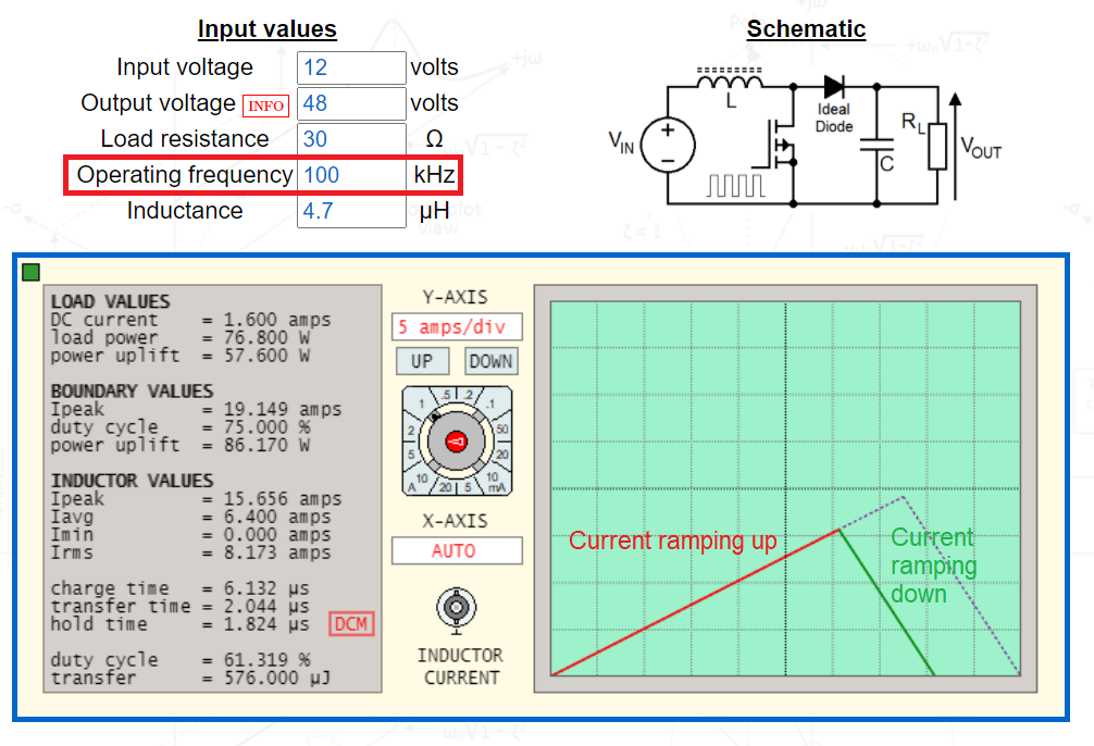
The point is that you don't hold the inductor connected to the incoming supply for more than a few microseconds (or a few tens of microseconds in really powerful boost converters). Here's an example of a boost converter's inductor current: -

enter image description here

Web boost-regulator calculator.

On the example above, current ramps up from 0 amps to 15.656 amps in 6.132 μs. It then transfers the energy (during which it ramps down) in 2.044 μs and, a little while later (1.824 μs), the cycle begins again. This is just one example and, we'd expect the incoming supply to be able to deliver 15.656 amps without drooping too much. This boost converter is operating in discontinuous conduction mode (\$\color{red}{\boxed{\text{DCM}}}\$) because the inductor current falls to zero before the cycle restarts.

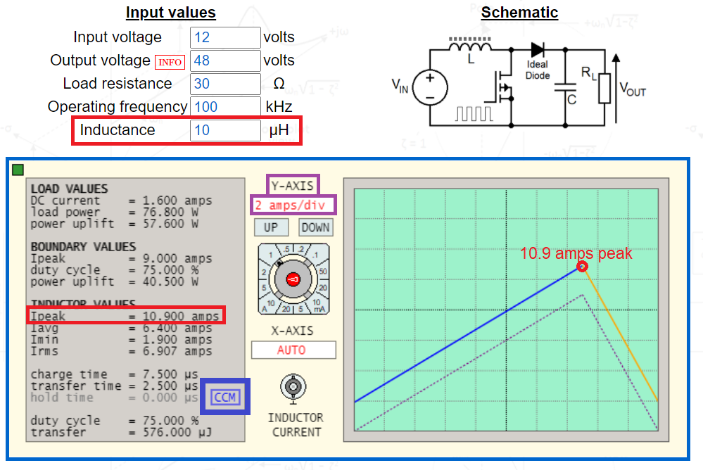
A larger value inductor (10 μH from 4.7 μH) means the current peak is less: -

enter image description here

Peak current is 10.9 amps and now the switching circuit is operating in what is known as continuous conduction mode (\$\color{blue}{\boxed{\text{CCM}}}\$) where the inductor holds on to a little bit of energy as the cycle starts again

\$\endgroup\$
2
  • \$\begingroup\$ Okay that makes sense. Thanks a lot! I think my confusion was caused by the plot for a resistor and inductor in series with a power supply that we learned a long time ago in a fundamental circuits course. Something like this hyperphysics.phy-astr.gsu.edu/hbase/electric/indtra.html In that case, the inductor voltage is changing because the resistor is taking more and more of the voltage drop as the current increases. However, in this boost converter, there is no resistance that will eventually take all the voltage from the inductor. \$\endgroup\$
    – John Allen
    Commented Feb 1, 2021 at 17:57
  • 1
    \$\begingroup\$ @JohnAllen push it too far and the internal resistance of the supply will eventually dominate but we avoid that by choosing a bigger inductor or higher operating frequency. \$\endgroup\$
    – Andy aka
    Commented Feb 1, 2021 at 17:59
0
\$\begingroup\$

Firstly, you have to assume that the inductor never saturates, i.e. it rises linearly according to the formula $$i = \frac{1}{L} \int V_{in} \,dt.$$

The integral of the input voltage is just a ramp signal so the current rises linearly during the on time of the switch.

As long as the inductor is not saturating, it generates a back EMF to oppose the rate of change in current according to Lenz's law. This back EMF is equal to Vin.

\$\endgroup\$

Your Answer

By clicking “Post Your Answer”, you agree to our terms of service and acknowledge you have read our privacy policy.

Not the answer you're looking for? Browse other questions tagged or ask your own question.