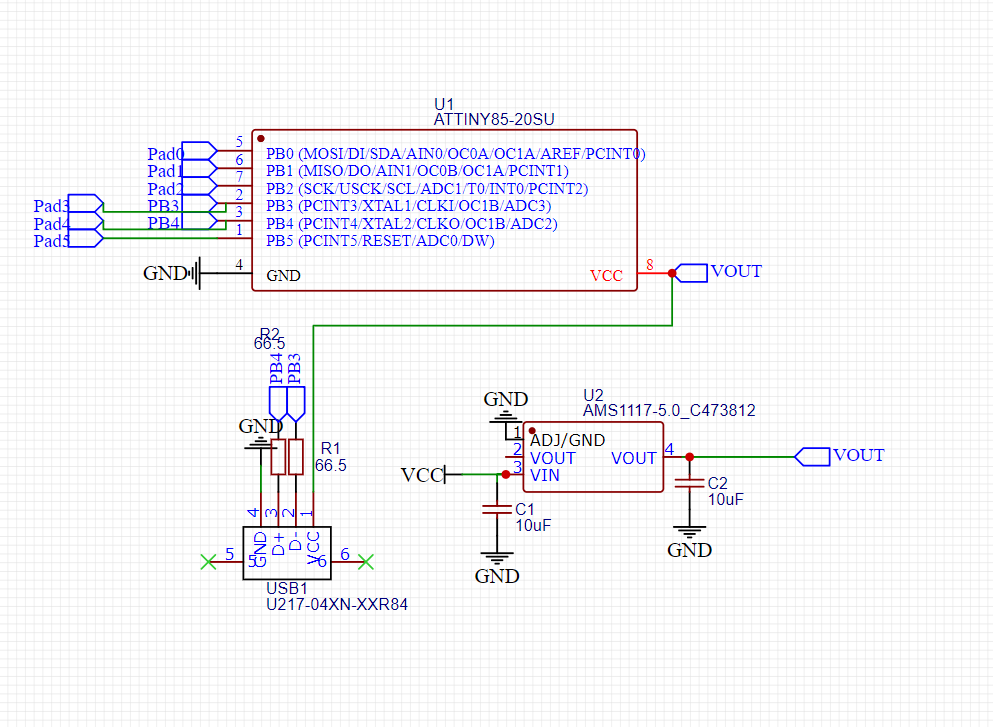
I was wondering if there is anything I am missing in this Attiny85 schematic. It will be first burned with the Arduino bootloader through the pins. I am making something similar to the DigiSpark attiny85
-
\$\begingroup\$ yes, the ground connections should be pointing downward as per schematic diagram drawing convention ... positive voltage at top, ground at bottom, negative voltages below that, inputs on left, outputs on right ... for example, the USB1 should be rotated 90 degrees clockwise and flipped vertically \$\endgroup\$– jsotolaCommented Feb 18, 2021 at 3:02
-
\$\begingroup\$ Yes. Plenty. Spend some and make a nice schematic. There’s no bypass caps. \$\endgroup\$– KartmanCommented Feb 18, 2021 at 3:04
2 Answers
There's a couple of things, aesthetics aside.
- The voltage regulator is unnecessary. The ATTiny can run on USB VBUS (5V) directly.
- Add at least one 0.1uf cap to the ATTiny VCC pin.
- It wouldn't hurt to add some protection diodes to the USB D+/D- pins.
- Programming header?
Here's a reference design from MIT... have a look: http://fab.cba.mit.edu/classes/863.16/doc/projects/ftsmin/index.html
Yes there are many problems. I will only focus on one in my answer, as most of them are mentioned already and are either very small technical issues or simply they should be drawn in another way.
The MCU is wired to run at 5V, and since USB data pins are 3.3V only signals, plugging this in can (and most likely will) damage the PC USB port and render it inoperable.
-
\$\begingroup\$ In the MIT ref they have 3.3V protection diodes on D+/D- \$\endgroup\$ Commented Feb 18, 2021 at 13:08
-
\$\begingroup\$ @hacktastical I have a question, have you ever heard of a USB rubber ducky? It is basically a device where you can emulate a keyboard from a usb drive. There is a attiny85 board called digispark which has its own arduino library where it can send key command through the usb port (which is PB3 and PB4). Now the usb data lines should be 3.3v. So what determines the voltage on PB3 and PB4? I would think that is the voltage you supply the microcontroller with right? So I should add a 3.3v regulator? \$\endgroup\$– user0456Commented Feb 18, 2021 at 20:29
-
\$\begingroup\$ @hacktastical and if there is a surge of voltage on the data lines above 3.3v which then means that is more than the reverse breakdown voltage on the zener diodes so it goes to ground and protects the usb port on the computer? Sorry if any of this is wrong \$\endgroup\$– user0456Commented Feb 18, 2021 at 20:30
-
\$\begingroup\$ A 3.3V regulator would make this circuit safer. However, lower supply voltage limits the speed the Tiny85 can run at, so it must be run at a lower frequency. So you then need firmware that is intended to run at lower frequency. Such a firmware may not exist yet, or the frequency may be so low that USB communication is not possible. You need to check carefully that if you do run at 3.3V, do you have the firmware to run at the lower speeds that at 5V. Zener diodes are not on/off devices. Should one become loose or you have a soldering error, a missing zener can be enough to kill the USB port. \$\endgroup\$– JustmeCommented Feb 18, 2021 at 20:36
-
\$\begingroup\$ @Justme Ok thats fine then I will run the attiny85 at 5v but then how do I limit the voltage in the usb data lines? Or are the gpio pins already at 3.3V? \$\endgroup\$– user0456Commented Feb 18, 2021 at 20:46

