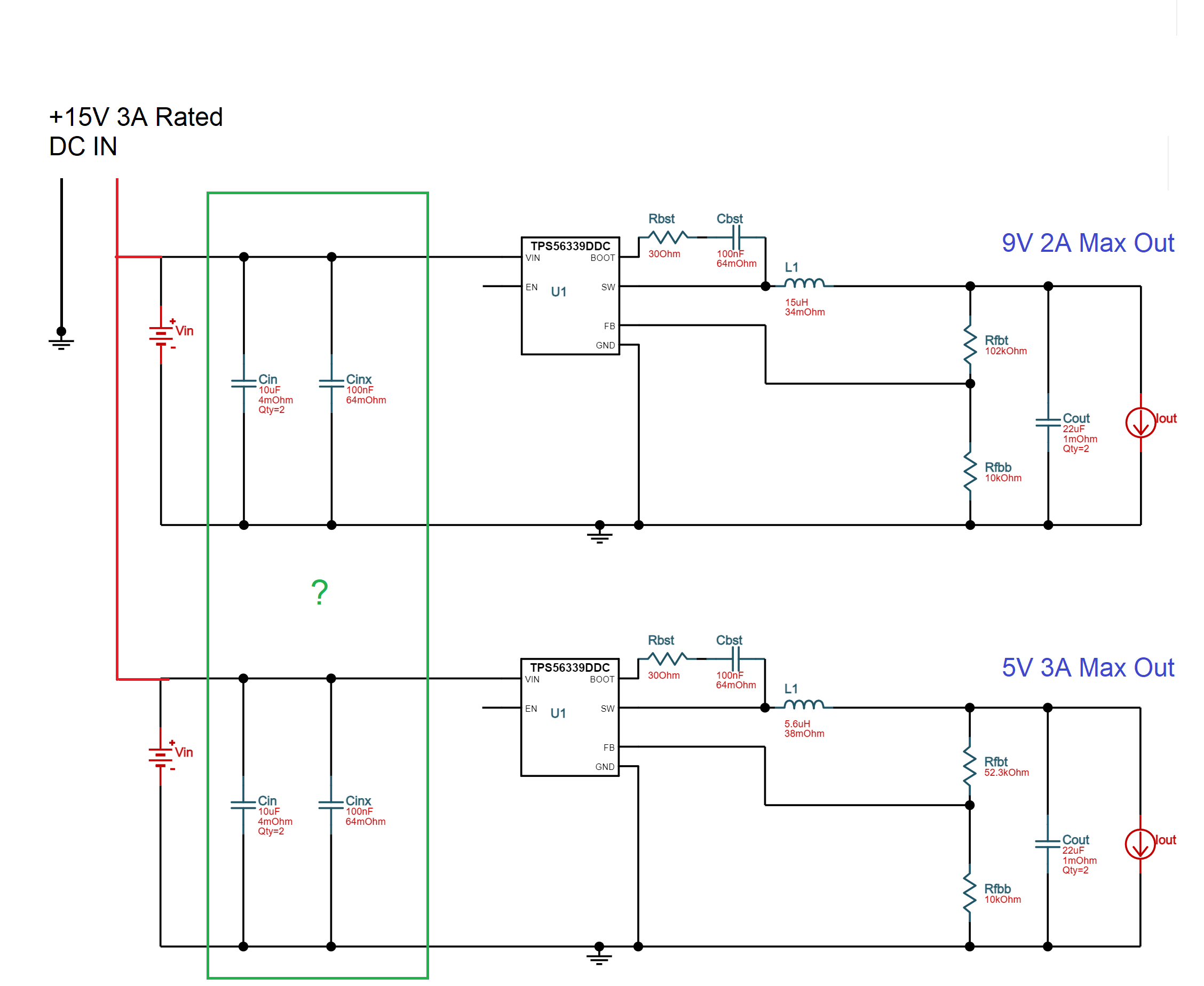
I've used TI Webench to implement single DC DC converters in a circuit, so I'm always confident in using whatever TI generates for me. But what are some design considerations or modifications required when combining two or more DC DC converters with different rated load? I was thinking this may need a change in the CIN, CINX components of the circuit. Or just leave as is? Here is a schematic with labels highlighting my concerns.
4 Answers
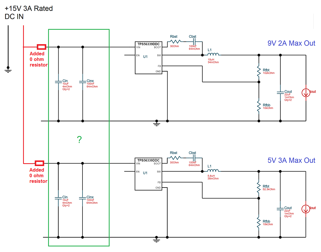
When doing something like this I wouldn't hesitate to make the required PCB with both capacitors fitted to both inputs and make room for a zero ohm resistor feeding each regulator. Make it an 0805 style resistor then, if you find that there is too much reflected noise back to the power supply with the resulting EMI problems, you can replace the zero ohm resistor with a small inductor or ferrite bead.
The inclusion of the zero ohm link also helps testing (in case of other problems that might short out the supply) by isolating each circuit.
You may find that you don't need to fit one of the 10 uF capacitors but, leave your options open when committing to PCB.
-
1\$\begingroup\$ Wonderful insight Andy! Never would I ever thought to do that! Thanks! \$\endgroup\$– allenCommented Mar 17, 2021 at 9:34
Typical designs with multiple switching converters either use a common clock for the switching frequency (but with phase offsets for each converter), or different switching frequencies that ideally aren't multiples of each other, to minimize the chance that both FETs turn on at the same time.
When you do that, you need less total capacitance on the input side, so they can probably share the 10uF, but I'd leave the 100nF in place on each leg, since that is what filters higher-frequency noise.
For unsynchronized converters with the same frequency, I'd leave the capacitors in place, and possibly even add a small inductor on each leg to improve the filtering.
In the worst case scenario, both loads require the maximum current.
That means that you should leave Cin and Cinx as they are now.
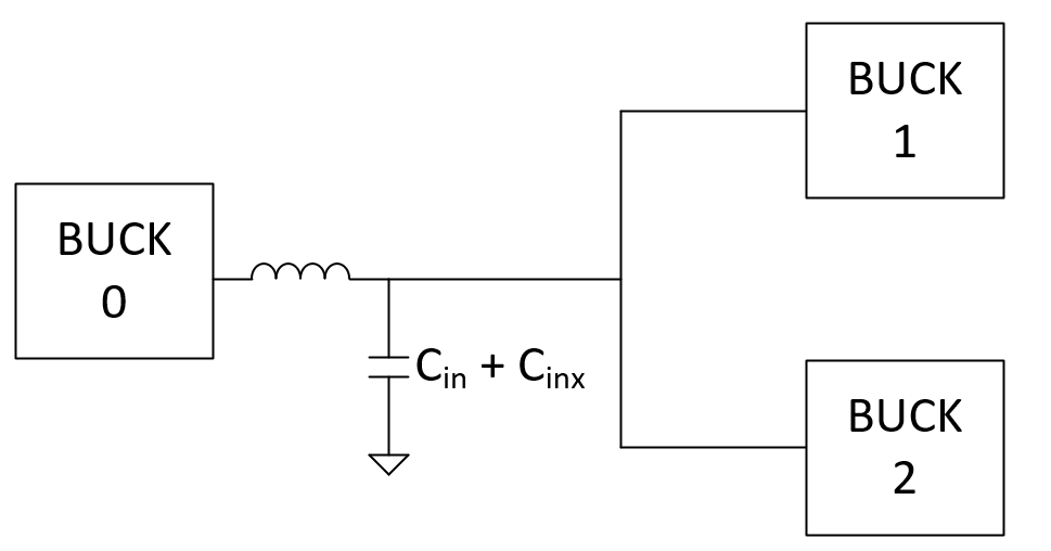
The input capacitance to both of your converters cannot be beyond the recommended value for output capacitance of the input power supply. Converters are loops and their stability is primarily determined by their LC output filter (in buck converters). Distribute capacitance equally not going beyond the max values recommended by the manufacturer.
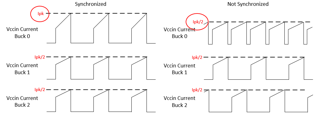
If the converters are synchronized you might have a problem of Vccin noise because of the current profile. See picture. This of course will also be dependent on your choice of inductor for buck 1 and 2.


