0
\$\begingroup\$

I'm trying to build a circuit that uses a non-inverting op-amp to double the voltage in the circuit. The op amp I'm planning on using is: http://www.farnell.com/datasheets/2258629.pdf , and I think it needs to be set up in this configuration: https://upload.wikimedia.org/wikipedia/commons/4/44/Op-Amp_Non-Inverting_Amplifier.svg. My question is what should the value of resistance of these resistors be? I know they have to be equal in value but am unsure about the absolute size of the resistance.

For reference the voltage going into the op-amp will be between 0-5V coming from an Arduino Uno power rail and varied through a potentiometer.

Thanks

Edit: The current circuit is as below, my thinking in response to the points raised about the voltage across the op-amp, is to put it in parallel to the proportional servo valve, hence running it off the 24V supply. My concern is that the current in that is 0.5A, which I understand wont all go into the op-amp, but the data sheet says the op-amp has a 2mA max limit. Does it have a feature built in that stops it accepting more than this, or will it try to accept more than this if given the opportunity and I'll end up breaking it?

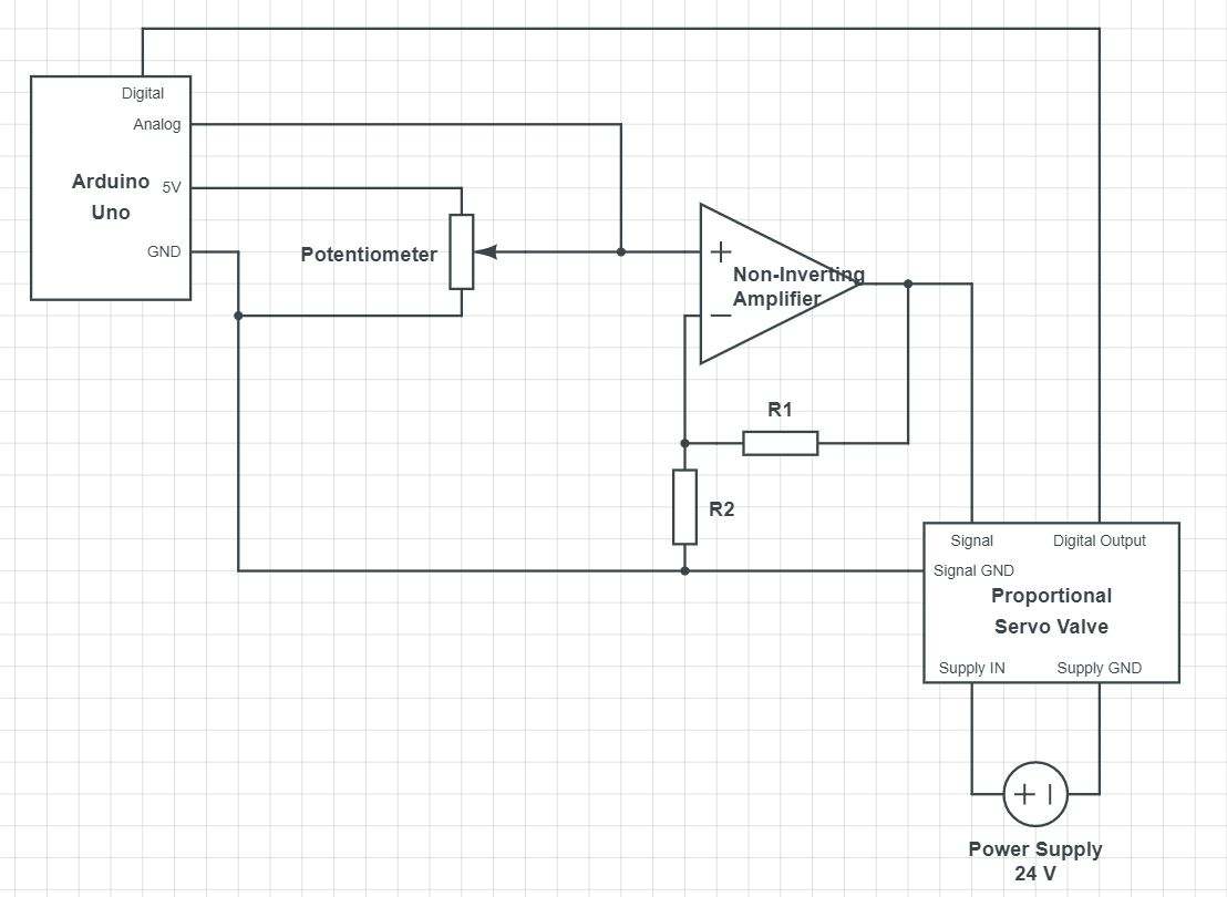
current setup

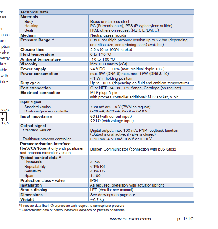
Valve Data sheet

\$\endgroup\$
6
  • \$\begingroup\$ Tip: when adding a hyperlink you can use the button or the link syntax [AB1234 op-amp](http://link.to.datasheet.com) syntax so that we know in advance what the part number is and don't need to follow the link if already familiar. The schematic should be posted inline again, so we don't have to follow a link and so the question still makes sense if the link dies. You may need to take a screengrab as Imgur doesn't support SVG. \$\endgroup\$
    – Transistor
    Commented Mar 31, 2021 at 17:10
  • 1
    \$\begingroup\$ Just to be clear, are you aware that if you power the op-amp from a 5 V supply that the most you can possibly get out is +5 V? It sounds as though you're hoping for 10 V out of the op-amp. \$\endgroup\$
    – Transistor
    Commented Mar 31, 2021 at 17:12
  • \$\begingroup\$ The most you can typically get out is 3 volts from a 5 volt rail AND, if the lower op-amp power rail is 0 volts then the lowest output voltage is 2 volts typically. That's a typical working range of 1 volt and not guaranteed to be that. Read the data sheet is my advice. \$\endgroup\$
    – Andy aka
    Commented Mar 31, 2021 at 17:18
  • \$\begingroup\$ So to get 10V out I would have to also have a power supply provide more than 10V to the pins over the op amp? \$\endgroup\$
    – M Shaw
    Commented Mar 31, 2021 at 18:19
  • \$\begingroup\$ Yes you would. Please edit to add in the servo valve datasheet link. \$\endgroup\$
    – Transistor
    Commented Mar 31, 2021 at 19:09

2 Answers 2

0
\$\begingroup\$

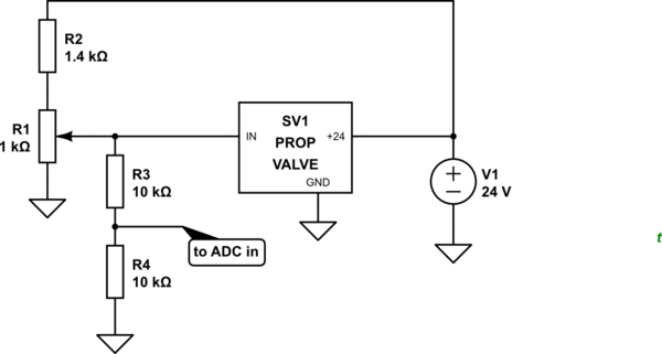
schematic

simulate this circuit – Schematic created using CircuitLab

Figure 1. Circuit modified after comments.

  • The device has a 0 - 10 V option.
  • You have a 24 V supply.
  • Adding R2 on the supply to R1 forms a potential divider. The maximum voltage out of R1 will be \$ \frac 1 {1 + 1.4} \times 24 = 10 \ \text V \$.
  • The pot can be adjusted from 0 to 10 V.
  • The R3-R4 potential divider gives 0 to 5 V feedback to the microcontroller.

That's it!

\$\endgroup\$
2
  • \$\begingroup\$ Hi Transistor, think I may not have explained this very well. The valve needs two voltage inputs into it: a 24V input to power it and a 0-10V input to control the state of it (open or closed or at a state inbetween). The point of using an Arduino was so I could measure the voltage (using an analog pin) that is after the potentiometer, then times this by 2 and get the 0-10 control voltage that is going into the valve. From this and the corresponding mass flow rate i would be able to construct a calibration curve of V-m_dot. \$\endgroup\$
    – M Shaw
    Commented Apr 1, 2021 at 8:41
  • \$\begingroup\$ See the update. Be aware that you are developing an open-loop control system and that you may be disappointed by the results. Monitoring the output pressure from your valve and using that to adjust the valve's setpoint would give superior control due to the feedback. \$\endgroup\$
    – Transistor
    Commented Apr 1, 2021 at 8:58
0
\$\begingroup\$

A good start for approximate range of resistor values in low-frequency op-amp circuits is 10K. That's because bias currents and leakage have little effect and they don't draw too much current from the op-amp output or from the inputs (where relevant, which isn't here).

You might go up by 10:1 or more if the circuit has to be very low power, you might go down by 10:1 or more if the circuit needs to be very low noise or high frequency.

That's just a rough rule of thumb. The details depend on the exact requirements, but often there's a fairly wide range of possible values.

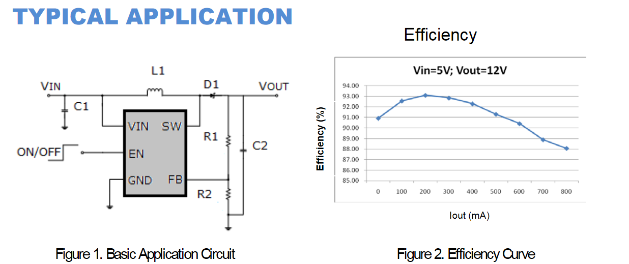
Of course, as Transistor mentions, to get 10V out you'll need a power supply of more than 10V, something like 12V is often enough. If you don't have a 12V supply, it can be created with a DC-DC boost converter.

enter image description here

\$\endgroup\$
3
  • \$\begingroup\$ That makes sense thank you. In regard to the power supple does the size of that matter, as in is there an upper limit it can go to? \$\endgroup\$
    – M Shaw
    Commented Mar 31, 2021 at 18:25
  • \$\begingroup\$ @MShaw What do you mean by "size"? Voltage, current? \$\endgroup\$ Commented Mar 31, 2021 at 19:56
  • \$\begingroup\$ Sorry yes I meant current into the op-amp. The specs sheet says it has a max operating current of 3mA, and I was wondering if it has an inbuilt limiter to stop it accepting more than that or if it was given the opportunity to take more than that if it would and in doing so break the internal component? \$\endgroup\$
    – M Shaw
    Commented Apr 1, 2021 at 8:43

Your Answer

By clicking “Post Your Answer”, you agree to our terms of service and acknowledge you have read our privacy policy.

Not the answer you're looking for? Browse other questions tagged or ask your own question.