7
\$\begingroup\$

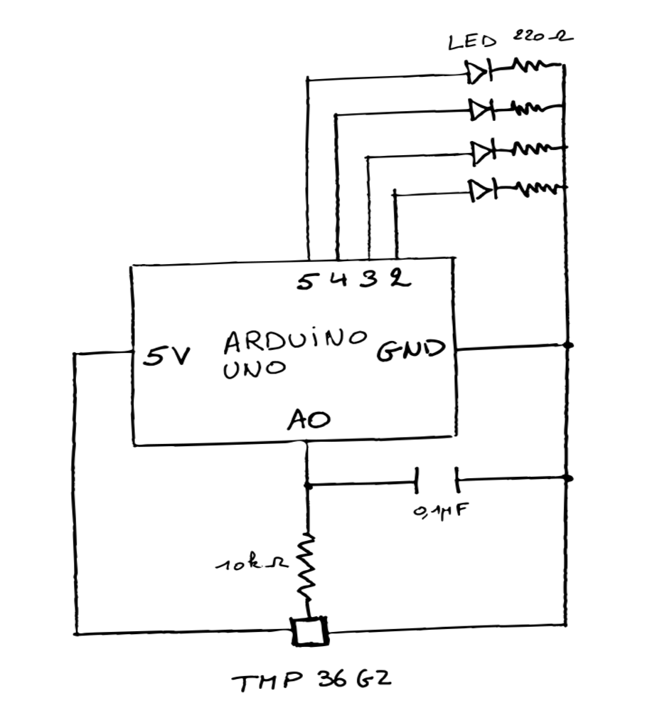
I'm trying to control some LED's (pins 2,3,4) with a temperature sensor. In the setup I do a calibration step to set the baseline temperature. When that's done, the LED at pin 5 is turned on.
Before I added the LED at pin 5, I already had some issues with the values I get from the sensor and this was fixed by the second answer of this post. I didn't have the capacitor and resistor with the same values as suggested, but it worked out fine.

After adding the LED at pin 5, I noticed that when the LED turned on, my sensor value jumped up a little.
Why does this happen and how can I fix this?

EDIT
Thanks for the answers, I tried a few of them, but they didn't work. I'm not sure if I did them correctly. I found this post and realized that the arduino board has multiple grounds. I got rid of the capacitor and the 10k resistor since they seem to do no effect. There's just a little jump after I turn on the LED at pin 5, but it's less. schematic
\$\endgroup\$
2
  • \$\begingroup\$ my sensor value jumped up a little - yeah that will happen or it could be jumped down a little. Really tricky to prevent little jumps. In fact the little jumps can happen all the time unless at absolute zero kelvin. \$\endgroup\$
    – Andy aka
    Commented Apr 1, 2021 at 14:25
  • 1
    \$\begingroup\$ You could use that as a feature to confirm that the LED is working: good LED = small jump, failed LED = no jump. \$\endgroup\$ Commented Apr 1, 2021 at 17:14

5 Answers 5

17
\$\begingroup\$

By default, the internal ADC of an Arduino / ATMega MCU uses the supply voltage as a reference. When you switch on a LED, more supply current is consumed and if your supply has some series resistance it could decrease a little bit in value.

Possible solutions are:

  • use the internal voltage reference for the ADC.

  • make sure that the current through the LEDs cannot affect the ground potential of the MCU, use a star ground connection.

  • use an (opamp based) amplifier to amplify the signal so you get for example 50 mV/°C instead of the 10 mV/°C directly from the sensor.

  • Make the connection between the supply regulator and the circuit short so with a low series resistance

  • Feed the Arduino with a 9 V supply (assuming it has a DC input for that) instead of through USB. If you use the DC jack then there's a voltage regulator on the Arduino to provide a stable internal 5 V which might help.

  • Separate the LED circuit, use MOSFETs (like 2N7000) to switch the LED's on/off. Then the current through the LEDs does not have to pass through the MCU, only through the MOSFETs and LEDs + series resistors. Combining that with the star ground way of connecting (also for the VDD!!) should help.

You can combine several of these suggestions.

\$\endgroup\$
2
  • 1
    \$\begingroup\$ One other way is reading VREF from the arduino itself. Set the input to the ADC to INTERNAL VOLTAGE 1.1V, and then measure it, from that you can then calculate what your VREF voltage is \$\endgroup\$
    – Ferrybig
    Commented Apr 3, 2021 at 13:56
  • \$\begingroup\$ @Ferrybig One other way is reading VREF from the arduino itself. Not sure what you're trying to achieve with that, my first suggestion is to use that internal VREF as the reference voltage for the ADC. Not sure how reading what the VREF is would help. \$\endgroup\$ Commented Apr 3, 2021 at 14:42
6
\$\begingroup\$

That is an analog sensor with an output of 10mV/°C so a change in ground potential will have an effect on the ADC reading of the sensor.

Make sure the GND common for the LEDs in your present circuit is run back to the power supply and not through the Arduino or any part of the sensor signal path.

You could also consider adding external drivers for the LEDs, such as a ULN2003A.

The ground for the LED drivers would be run back to the power supply and the ground for the sensor to the Arduino.

\$\endgroup\$
6
\$\begingroup\$

An arduino uno is not the most noise free board for analog signals. The arduino does not separate or filter the analog section of the atmega microcontroller from the digital side. Depending on what you are doing, pwm, dirty input voltage, high current via a pin causing voltage droop or rise, etc your analog readings are going to vary.

A proper board for analog reading would have a decoupled digital ground and analog ground planes with an LC filter per the ATmega datasheet. @Bimpel's answer has even more hints. At some point though you are chasing diminishing returns.

You should try using averages of your sensor instead of single reads. The ADC likely has some calibration or setup time as well. Doing 3 reads in a row and taking the mid value may result in cleaner value history.

\$\endgroup\$
1
\$\begingroup\$

Depends how big the jumps are.

Your sensor outputs a signal which changes by 10mV per °C.

The Arduino Uno really isn't great at measuring small changes like these. It has a 10-bit analog-to-digital converter, which means it can measure 2^10 = 1024 different voltage levels. Over a range of 0V to 5V this gives you a resolution of about 4.9 mV (5V / 1024), which translates to about 0.5°C.

This means you should always expect little jumps up and down by 0.5°C which are due to the rounding errors amplifying the noise. If you look at the raw integer value from the analogRead(), you'll see it changing exactly by 1. The solution for this is to average the float values in °C over time in software.

If you see bigger jumps you might want to look for other causes of noise. The application notes for your sensor calls for a decoupling capacitor which seems to be missing in your circuit; I would suggest fixing this first. See the paragraph starting with "Note the 0.1 μF bypass capacitor on the input" on page 10, and pay attention to the placement and the type of capacitor (an electrolytic probably won't work).

If you need a higher precision and you are stuck with the Arduino Uno, I would suggest using a digital temperature sensor instead, you can find plenty of modules with 16 bits of resolution.

\$\endgroup\$
0
\$\begingroup\$

A possible workaround which requires no hardware modification is to measure the temperature only while all LEDs are off. You will likely have naturally occurring states in your programs when no LEDs are powered (or at least not all of them are powered simultaneously). Use those states to read the temperature and store it for future use.

If all LEDs stay on for a long time, you could briefly switch them off, measure the temperature, and switch them on again. If you do it fast enough, the switch off will not even be visible.

\$\endgroup\$

Your Answer

By clicking “Post Your Answer”, you agree to our terms of service and acknowledge you have read our privacy policy.

Not the answer you're looking for? Browse other questions tagged or ask your own question.