0
\$\begingroup\$

I am trying to look for a solution that can help me in turning ON/OFF my 24VDC, 2A LED load. So as per the application needs I may have to turn ON/OFF this load 30 times max per day. So it is a DC operation.

Below sketch shows a quick pictorial representation of what I am trying to do. Not a final layout yet.

enter image description here

I am looking if I can use a MOSFET rather electro mechanical relay. I am referring to the ROHM RQ7L050AT datasheet. This is a 60V, 5A Mosfet.

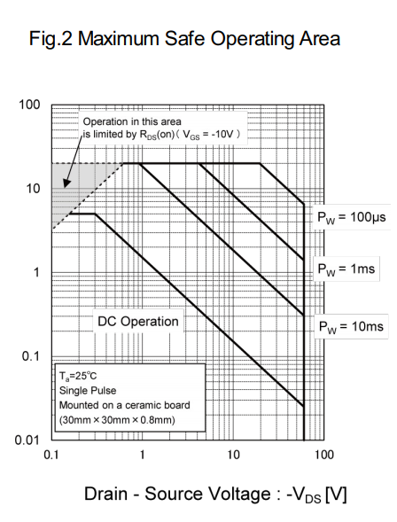
But by looking at the SOA curve as below, I am not sure if this MOSFET approach is advisable for continuous DC loads.

As per the graph, I guess at the desired 24VDC VDS the maximum allowed Id current is less than 0.07A before I hit the thermal runaway situation? (whereas my actual requirement is for 2A Id).

Let me know if I am getting if right. Can anyone help me understanding the MOSFETs for DC load operations?

Will it help if I choose higher VDS and Id rated MOSFETs?

enter image description here

Thanks in advance!

-Yugandhar

\$\endgroup\$

2 Answers 2

1
\$\begingroup\$

VDS depends on the current and the resistance of the MOSFET.

Your RQ7L050AT has a maximum RDSON of 39 milliohms. At 2 amperes of current, that's a VDS of less than 0.1 volts.

0.1V and 2A is well within the safe operating area for continuous DC.

You've got a Zener diode in there protecting the gate from the 24V. The NZX84C10L should keep the gate voltage below 11V, so the gate is safe.

\$\endgroup\$
1
  • \$\begingroup\$ Oh I got it now! I was assuming the other way round, that VDS is the OFF state voltage of the mosfet drain-source. Thanks for clarifying. \$\endgroup\$ Commented Apr 20, 2021 at 14:40
0
\$\begingroup\$

When fully ON your Vds will be around 80mV (39mOhm*2A), which is inside your safe operating area. However you must consider this is with the MOSFET mounted on a ceramic plate for dissipation. This MOSFET mounted on a PCB with no dissipation will not handle the current of your application.

enter image description here

\$\endgroup\$
1
  • \$\begingroup\$ Thanks! So in the datasheet, the Rthj-a was mentioned as 113degC/W (for FR4 PCB base of 25x25mm). However I could not find the Rthj-c in the datasheet. So in the worst case, I can assume 113degC/W as my thermal resistance? \$\endgroup\$ Commented Apr 20, 2021 at 14:52

Your Answer

By clicking “Post Your Answer”, you agree to our terms of service and acknowledge you have read our privacy policy.

Not the answer you're looking for? Browse other questions tagged or ask your own question.