0
\$\begingroup\$

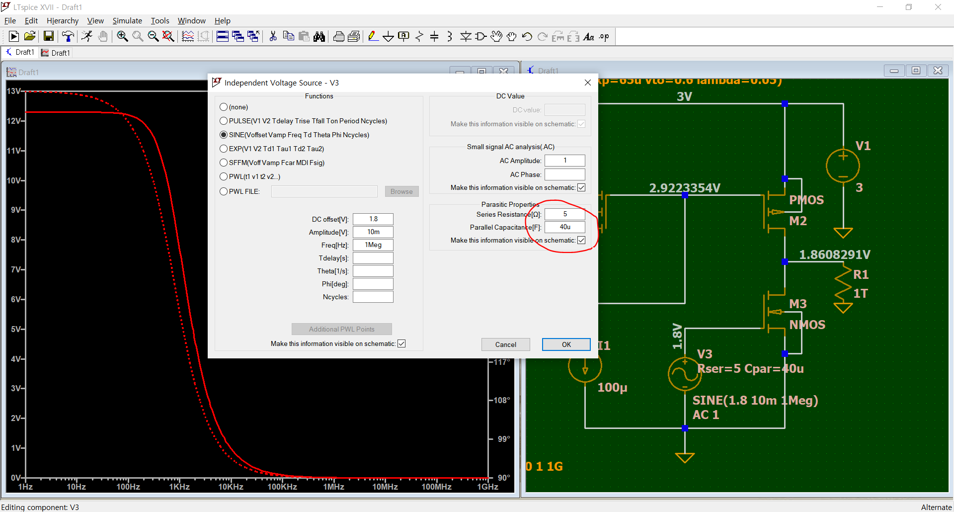
Figure1

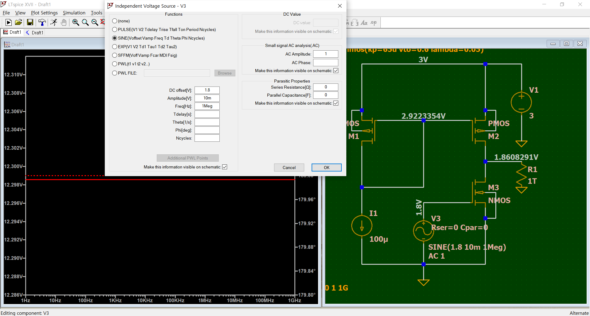
I am simulating the Common source amplifier circuit with current mirror. I wanted to see the frequency reponse of this circuit. And I got the constant value as you see the upper graph.

Figure2

I have finally noitced if I change the value the parastic properties at Input Voltage Source, It shows the curve similar as I expected.

I want to ask you I'm on a right way to do AC simulation, And How should I set the parasitic properties. Thank you.

\$\endgroup\$
2
  • 1
    \$\begingroup\$ Your first circuit is composed of only ideal(ized) components. As you have not any capacitors there, the frequency response is constant. The second circuit received capacitances, only indirectly, added to your components through the parasitics option. For you are seemingly at the introductory level, start with examining circuits composed of only ideal(ized) components. When you advance in circuit design and master the LTspice, you can use models of real components, but first use (ideal) capacitors as individual components and refrain from using parasitics feature for a while. \$\endgroup\$
    – V.V.T
    Commented Apr 25, 2021 at 4:33
  • 1
    \$\begingroup\$ The second response is due to the parasitics you added to the source. Look up the help under LTspice > Circuit Elements > M. MOSFET for the first table, in particular the Cxxx parameters. If you don't know what exactly they represent, it's better to read first about them, instead of just blindly throwing them at the screen. \$\endgroup\$ Commented Apr 25, 2021 at 7:19

1 Answer 1

3
\$\begingroup\$

It appears that the NMOS / PMOS models you have chosen do not have any frequency-dependent effects. The rest of your circuit also has no capacitors or inductors. As a result, the gain of the circuit is independent of frequency. Therefore, the plotted frequency response is a flat horizontal line.

From your schematic screenshot, there is a line cut off at the top that says (kp=... vto=... lambda=...). All three of these parameters (kp, vto, and lambda) specify only the DC behavior of a MOSFET.

You'll need to add other parameters to specify frequency-dependent effects.

See LTspice MOSFET model help to learn more about these parameters. Alternatively, you can use a pre-made MOSFET model that already includes these parameters.

\$\endgroup\$
2
  • \$\begingroup\$ I understood your point. I downloaded MOSFET Bsim4 model from this website. "cmosedu.com/cmos1/book.htm". After I include this file at the LTspice, I saw the frequency response in which gain is diminished when the frequency increases. \$\endgroup\$
    – fluencer
    Commented Apr 27, 2021 at 22:14
  • \$\begingroup\$ May I ask you answer this question, compumlike? electronics.stackexchange.com/questions/562438/… \$\endgroup\$
    – fluencer
    Commented Apr 27, 2021 at 22:40

Your Answer

By clicking “Post Your Answer”, you agree to our terms of service and acknowledge you have read our privacy policy.

Not the answer you're looking for? Browse other questions tagged or ask your own question.