0
\$\begingroup\$

I want to build a system to measure the time of flight for a long transmission line. The length of the transmission line is between 500 m and 3 km. The attenuation of the transmission line is 0.00981 dB/m. The impedance of the transmission line is 150 ohm. A 3 V pulse fed into a 3 km long transmission line will lead to a reflection with an amplitude of 100 mV. I want to measure the time of flight. From previous measurements I know that the signal needs 1 ns to travel 20 cm.

My goal is to determine the length of the transmission line with a accuracy of 10 m.

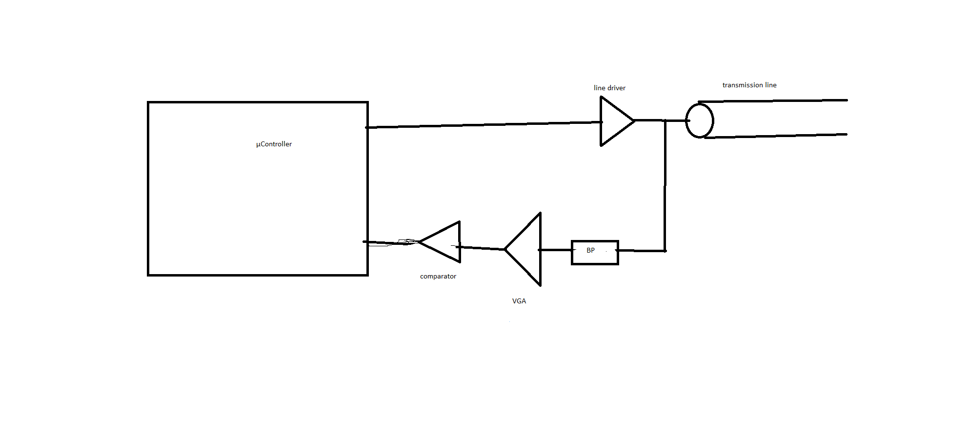
My approach is to drive the transmission line with a high current output opamp, that outputs a 5 ns pulse with an amplitude of 3 V. Since the signal will be attenuated along the way, I am using a VGA (variable gain amplifier) to amplify the signal to around 3 V, so it can be read by a µController. Infront of the VGA I am planning to place a Bandpass filter, to get rid of the noise floor and possible DC offsets. The passband will be from 200 MHz (1/5ns) to 2 GHz. I know that the bandpass filter will lead to a decrease in accuracy since the edges will become less "sharp" but thats negligible. Infront of the VGA I placed a comparator to prevent switching uncertainties.

enter image description here

My problem now is:

The reflected pulse can either have a positive or a negative polarity, depending if the transmission lines end is short circuit or open end.

So I am trying to detect a pulse with a width of 5 ns that can have a negative polarity (short circuit at the end of the transmission line) but also a positive polarity (open end transmission line). The pulse occurs every 30 seconds. The voltage is 3 V, the current is 100 mA max.

What is the best way to detect this pulse with the best accuracy possible?

\$\endgroup\$
23
  • \$\begingroup\$ 30 seconds is irrelevant. Take a look at a datasheet for RF Schottkys and do some simulations. 30 V and 5 ns is going to be a big challenge. \$\endgroup\$
    – winny
    Commented Jun 18, 2021 at 13:10
  • \$\begingroup\$ @winny it is 3V and 5ns. Maybe I should use opamps as a full bridge rectifier? \$\endgroup\$
    – Yoomo
    Commented Jun 18, 2021 at 13:11
  • 1
    \$\begingroup\$ OK, now it's getting confusing. Could you edit your question and describe your overall system? This feels a lot like you're trying to build a receiver for some specific differential signalling standard that was almost certainly designed with some specific receiver in mind, but you're trying to (suboptimally) re-invent the wheel. \$\endgroup\$ Commented Jun 18, 2021 at 13:24
  • 3
    \$\begingroup\$ It may be easier to set up two detectors, one for positive and one for negative pulses. \$\endgroup\$ Commented Jun 18, 2021 at 14:24
  • 1
    \$\begingroup\$ @Yoomo a fast diode is defined as "fast enough to deal with your signal": you'll need to read datasheets. \$\endgroup\$ Commented Jun 18, 2021 at 14:50

2 Answers 2

2
\$\begingroup\$

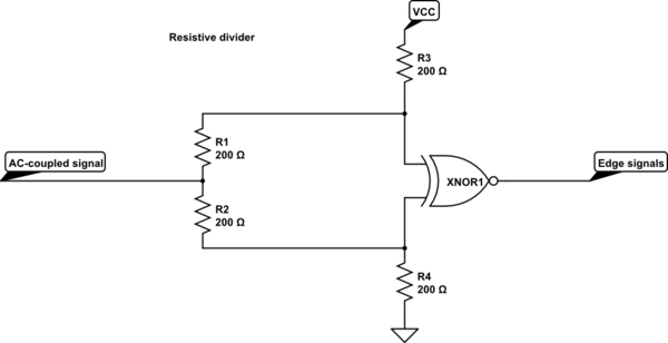
schematic

simulate this circuit – Schematic created using CircuitLab

should do it.

Idea: an XOR is 0 when both inputs are the same, and 1 when they are different. XNOR inverts that: 1 if both are same, 0 if the inputs are different.

Since your input is AC coupled, as long as nothing happens, the upper input of the below circuit is at VCC · 3/4, and the lower one is at VCC · 1/4, so, one is high, the other low, and the output is 0.

When you get a positive pulse, it shifts the already positive input further up, so that input stays high, but it also shifts the lower input up, so it becomes high; now, both inputs are the same, and the XNOR outputs a 1.

When you get a negative pulse, that shifts your upper input down, so you get a low input on your upper input, and the lower input becomes even lower, so stays low. Both inputs are now low, XNOR outputs a 1.

Note that this relies on the protection diodes of your XNOR gate to deal with a bit of overvoltage, and undervoltage. Very often, that's not a problem. If it becomes a problem, a USB3 ESD diode array might be used to add needed protection.

It also relies on the signal level being high enough to shift these inputs – but the required sensitivity can be achieved through adjusting the resistor values.

\$\endgroup\$
24
  • \$\begingroup\$ the problem with a XNOR gate is that the propagation delay is really high \$\endgroup\$
    – Yoomo
    Commented Jun 19, 2021 at 11:11
  • \$\begingroup\$ a) define "really high": I bet you're just looking at an old XNOR gate. Also, even if it were: b) that's not a problem at all. You don't need low propagation delay. In fact, you don't care about delay, at all: It's just a fixed delay that you need to subtract, just as you need to subtract the group delay through the rest of your circuitry. So, that's not even an extra step during calibration. \$\endgroup\$ Commented Jun 19, 2021 at 11:18
  • \$\begingroup\$ I looked up XNOR gates with the lowest delay on mouser, the lowest delay was 25ns. The delay is also dependent on the temperature. Lets say the delay at 25°C is 25ns, how big is the delay at 40°C? \$\endgroup\$
    – Yoomo
    Commented Jun 19, 2021 at 11:29
  • \$\begingroup\$ yeah, I don't know how you've found that, but three clicks on TI.com led me to XOR gates with < 5 ns delay, and since you can use an XOR gate as inverter, that means you can build a < 10 ns XNOR out of these. So, indeed, you're looking at old technology. Anyway, you're still very right - the moment your calibration needs to incorporate temperature, things get complicated. How well can you control the temperature of the cable under test? Because, you don't need to make your measurement device better temperature-controller or -compensated than you can control your tested object. \$\endgroup\$ Commented Jun 19, 2021 at 11:41
  • 1
    \$\begingroup\$ Anyway, the datasheets of these higher-speed XOR gates do specifiy the delay range over the whole operating temperature range (e.g. the SN74AUC2G86 datasheet says it's 0.3 ns to 1.3 ns – which means that you calibrate once, and then have a sensor that says "sorry, temperature of measurement device outside 15–40° C, performance degraded", and probably get some 0.1 ns accuracy... Compare that to the immense uncertainty that you'd get with an uncompensated diode bridge. Maybe you should start your questions by stating the requirements you have before discussing an option to achieve them! \$\endgroup\$ Commented Jun 19, 2021 at 11:45
3
\$\begingroup\$

I know that the signal needs 1ns to travel 20cm.

$$\frac{20\,\text{cm}}{1\,\text{ns}}=\frac{2\cdot10^{-1}\,\text{m}}{10^{-9}\,\text{s}}=2\cdot10^8\frac{\text{m}}{\text{s}}$$

just as expected from a transmission line, roughly 2/3 of the vacuum speed of light. However: this has at most two significant digits, i.e. you get at least 1% of error if your speed measurements aren't accurate. You want 10m accuracy over 3 km, that's 0.033% of error.

Measuring your signal speed accurately makes or breaks your whole measurement.

My goal is to determine the length of the transmission line with a accuracy of 10m.

So, you need to measure timing to an accuracy of 50 ns! (and you were complaining about logic gates with a few ns of delay uncertainty...)

500m and 3km

So, rundtrip times of 2.5 µs to 15 µs.

OK, this gives us a lot to work off!

drive the transmission line with a high current output opamp, that outputs a 5ns pulse with an amplitude of 3V.

Oh! I wouldn't recommend that; totally wrong. An opamp is useful if you need something that amplifies the input nice and linearly. You don't want that. You want the sharpest edge you can get.

So, opamp: would need fantastic (significantly more than 1GHz!) bandwidth.

Instead, a simple CMOS push-pull stage with a MOSFET driver will give you an excellent sharp edge.

You will want to add a 150Ω series resistor to match the impedance of your MOSFETs (which will be very low) to the transmission line.

The duration of the pulse doesn't matter, by the way, for your system. What matters is the steepness of its edges. (Which are inverse to its bandwidth.) You can measure the distance just as accurately with a 20s duration pulse as with a 5ns pulse, as long as the bandwidth of the edges are the same!

I am planning to place a Bandpass filter

Excellent!

A band-pass filter filters away low frequencies. If you design it such that the lower cut-off frequency is above 1/(pulse duration), then you get something that resembles the derivative of your pulse. Instead of seeing a rising and a falling edge, you get two pulses where the edges are!

Read this carefully, and make yourself a drawing of voltage over frequency! Draw a pulse (with slightly round edges, ca 1ns wide, 5ns long pulse), and then, same size, draw the derivative of that function.

That derivative plot should now be a figure with two pulses, one when the rising edge of the original pulse is, one when the falling edge of the original pulse is.

Now, do the same thing, but for an inverted pulse: Now you get one pulse, negative, for the first edge, and one, positive, pulse for the second edge.

See what I'm doing here?

The highpass part of your bandpass filter just converted your positive and negative pulses into a signal where there's always a positive pulse.

So, you don't need a rectifier at all. Forget the rectifier! It makes things harder, and doesn't help you at all!

Great, now you only have to detect that pulse. A high-speed comparator might indeed do that. But with a single NPN transistor you can do the same: since this is all AC-coupled, your pulses are around any arbitrary DC voltage you choose.

So, a single transistor can be used to amplify your signal enough so that it can be directly observed by your microcontroller.


So, there we go, your whole system would then be:

  • microcontroller to generate the pulse
  • a CMOS pair to buffer the pulse and feed it into the transmission line through a 150Ω resistor
  • a bandpass filter to convert the pulse into two pulses at the edges
  • three resistors and a 10ct NPN with enough bandwidth
  • your microcontroller to observe the amplified positive pulse

That's it! No opamps, no comparators, no rectifiers, no logic involved here – just very basic signal theory and using the right amplifier for the job.

\$\endgroup\$
5
  • \$\begingroup\$ thank you, really good ideas. But the NPN transistor has to amplify the signal to 3V, so it can be observed by the µController. The pulse comes with different voltages depending on the length of the transmission line. I would need to design a automatic gain control for this, right? \$\endgroup\$
    – Yoomo
    Commented Jun 19, 2021 at 14:18
  • \$\begingroup\$ no, not right. Why would you? That thing needs to saturate to the microcontroller's IO voltage, that's all. Also, you literally have less than 10 dB of dynamic range. So, a single transistor, it is. \$\endgroup\$ Commented Jun 19, 2021 at 14:19
  • \$\begingroup\$ ah ok, so it outputs always the IO voltage when its saturated to the µcontrollers IO Voltage \$\endgroup\$
    – Yoomo
    Commented Jun 19, 2021 at 14:21
  • \$\begingroup\$ you suggested me to drive the transmission line with a CMOS push pull stage and a MOSFET driver. So I will need 3 MOSFETS in total. Why do I need that additional MOSFET driver, isn't the push pull stage enough? Do I need to consider something special when choosing the MOSFET? I think I just need a high current output to overcome the capacitance of the line \$\endgroup\$
    – Yoomo
    Commented Jun 22, 2021 at 19:21
  • \$\begingroup\$ isn't the push pull stage enough to drive the line? \$\endgroup\$
    – Yoomo
    Commented Jun 23, 2021 at 11:05

Your Answer

By clicking “Post Your Answer”, you agree to our terms of service and acknowledge you have read our privacy policy.

Not the answer you're looking for? Browse other questions tagged or ask your own question.